|
Schmidt Consulting |
|
Window Ventilation Controller |
|
|
|
|
|
Tom Schmidt |
|
6/23/2015 |
|
Our house has a pair of south facing awning clearstory windows; the controller automatically opens the window and turns on exhaust fans during the summer whenever it is warmer inside then out. |
Table of Contents
WebControl Programmable Logic Controller
Appendix B – WebControl Configuration Pages
Appendix C – WebControl PLC Code
Overview
Our house has a pair of south facing clearstory awning windows. Here in southern NH most summer nights cool down substantially creating an opportunity for passive summer cooling and ventilation. When I designed the house hoped simply leaving the windows open in summer would move enough air to cool the house down to near morning outdoor temperature.
Unfortunately that scheme did not work as well as I had expected. Leaving the window open during the day allows hot air heated by the south facing roof to enter the house. At night even with a significant temperature differential by morning inside air is still much warmer than outdoor. The solution was an active system to control the window so hot daytime air is prevented from entering the house and using exhaust fans to increase nighttime air movement to do a better job cooling off the interior.
Design Goals
I used the same WebControl PLC I’ve used for other projects as the brains of the system. It supports multiple Dallas/Maxim 1-wire temperature sensors to measure indoor and outdoor temperature. That allows differential temperature to control the windows. As long as outdoor temperature is warm enough whenever inside temperature is higher than outdoor the controller automatically opens the windows and turns on the exhaust fans. The system supports control of two windows, although the initial implementation is a single window.
The actuator is pretty strong so I wanted to include provisions to detect a jam and recover if possible.
A rain sensor overrides normal operation to close the window during rain storms. A web based configuration page selects manual or automatic operation and sets the exhaust fans to high or low.
Window Actuator
 The heart of
the system is a motorized window actuator. Finding one turned out to be much
harder than I expected. I wanted to use a motorized chain drive actuator
similar to the manual arrangement we have for our bathroom skylight. Even
though the chain is flexible because both ends are fixed it provides a rigid
arm to extend and retract the window. When retracted the chain is coiled up
within the actuator housing. Electric window operators typically contain a
built in microcontroller. The DC units are two wire devices. One polarity opens
the window the other closes it. The internal controller also senses motor current
and shuts the unit down at full extension and retraction or if it detects a
jam.
The heart of
the system is a motorized window actuator. Finding one turned out to be much
harder than I expected. I wanted to use a motorized chain drive actuator
similar to the manual arrangement we have for our bathroom skylight. Even
though the chain is flexible because both ends are fixed it provides a rigid
arm to extend and retract the window. When retracted the chain is coiled up
within the actuator housing. Electric window operators typically contain a
built in microcontroller. The DC units are two wire devices. One polarity opens
the window the other closes it. The internal controller also senses motor current
and shuts the unit down at full extension and retraction or if it detects a
jam.
An Internet search turned up several distributors but they were all in Europe. Actuator cost was high and shipping came close to doubling the price. I finally found a US/Canadian company RollerTrol that makes electric actuators for both windows and blinds. Their support was staff was extremely helpful. The cataloged item operates at 12 volts but they have a special order version that operates at 24 volts. I wanted to use the higher voltage because that is what I needed for the fans and to reduce current through the H-bridge IC used to control actuator direction.
Since the awning windows were not very tall I was worried the standard full extension range 11 - 13/16” (300mm) was too great so they were able to reduce throw to 9 -7/8” (250mm).
Fans
 I found some
surplus Rotron and Papst 6.75” 24 volt fans to provide the exhaust function.
Each awning window is 4 feet long and 1’-7” tall. Mounted four fans per window
in a high/low arrangement where the controller turns on two fans for low and all
four for high. The fans are mounted on a polycarbonate sheet on the inside of
the window, with the fans located between the polycarbonate sheet and the
removable window screen. This arrangement keeps bugs out when the fans are not
running and lets in as much daylight as possible.
I found some
surplus Rotron and Papst 6.75” 24 volt fans to provide the exhaust function.
Each awning window is 4 feet long and 1’-7” tall. Mounted four fans per window
in a high/low arrangement where the controller turns on two fans for low and all
four for high. The fans are mounted on a polycarbonate sheet on the inside of
the window, with the fans located between the polycarbonate sheet and the
removable window screen. This arrangement keeps bugs out when the fans are not
running and lets in as much daylight as possible.
Window Mockup Test Jig
 The design of
the controller was part of a larger project to replace our windows. To
facilitate debugging the controller I built a crude mockup of an awning window
that mounted the actuator, four fans and a switch to detect when the window is
fully closed.
The design of
the controller was part of a larger project to replace our windows. To
facilitate debugging the controller I built a crude mockup of an awning window
that mounted the actuator, four fans and a switch to detect when the window is
fully closed.
During early debug used a small pilot light to indicate when power was being applied to the actuator.
Test jig proved to be extremely valuable; while it did not fully replicate the actual window it provided a good first approximation. Once I had basic open/close and fan control code debugged worked on jam detection. This is an important safety consideration as the actuator has about 20 lbs. (9 kg) of force so if your hand gets caught while the window is closing it is going to hurt. Based on results using the test jig I changed the window closed sensing switch from a magnetic reed to mechanical micro switch. The micro switch is able to deliver accurate detection of window closed position. This was critical for detecting jams during close operation.
Temperature Sensing
Three of the 8 PLC temperature channels are used. Channel 1 is outside air temp near the window, channel 2 is inside temperature near the window and channel 3 is temperature within the chassis itself. Code processes indoor and outdoor temperature deferentially. Assuming outdoor temperature is high enough when indoor temperature exceeds outdoor the windows are opened. The third temperature sensor monitors temperature within the chassis. This is not used by the automated process but provides a way to detect excessive internal chassis temperature.
Relative Humidity Reporting
 WebControl
supports the Honeywell HIH-4000 humidity sensor. This provides a highly
accurate reading of relative humidity. Humidity is not used by the control
system it is simply displayed on the web interface.
WebControl
supports the Honeywell HIH-4000 humidity sensor. This provides a highly
accurate reading of relative humidity. Humidity is not used by the control
system it is simply displayed on the web interface.
 WebControl
Programmable Logic Controller
WebControl
Programmable Logic Controller
One of the nice aspects of the CAI networks WebControl is that it includes a built in web server. This allows any PC on the LAN to monitor window ventilator status and multiple temperature measurements.
The device provides 8 digital inputs, 3 10-bit analog inputs, 8 digital outputs, up to 8 Maxim/Dallas 18B20 1-wire temperature sensors, and a humidity sensor using a Honeywell 4000. WebControl implements a simple scripting language. User code is generated offline and pasted into the system.
System Status
The System Status screen displays various values and registers. VAR 1 is overall system hardware health status and is used to report power supply and temperature sensor faults, VAR2/3 report status of each window. The Input and Output bits display the various digital controls.
 |
Temperate and relative humidity readings are displayed on the status page. Due to a wiring screw up analog 1 reports window 2 current, analog 2 is window 1, it was too much work to correct. Analog 3 is ½ the 5V from buck converter. It is on when the 24V supply it enabled, this is used to provide a sanity check of the 24volt subsystem.
 |
To make the status display easier to interpret when there is a hardware fault the notification email includes a list of status codes for the system and individual windows.
Backup Actuator Power Supply
 I was worried a
controller failure would leave the window stuck in the open position. As
insurance I obtaining a small 24V power supply and mounted a spring loaded
center off DPDT reversing switch to a bracket. If I ever need to operate the
actuator manually I can disconnect it from the controller and use this as a
backup. It also came in handy debugging the op amp circuit rather than issuing
software commands to the controller.
I was worried a
controller failure would leave the window stuck in the open position. As
insurance I obtaining a small 24V power supply and mounted a spring loaded
center off DPDT reversing switch to a bracket. If I ever need to operate the
actuator manually I can disconnect it from the controller and use this as a
backup. It also came in handy debugging the op amp circuit rather than issuing
software commands to the controller.
Installation
The actuator and fans are installed on a Marvin Integrity awning window. The controller was designed to support two windows; so far I have only installed a single window.
The windows have a central operating mechanism and a left and right hand locking levers. I removed the manual operating mechanism and installed the electric actuator. This was fairly difficult as there was very little vertical height available. I removed the bottom trim panel to give me access to the lower jam and the mounting screws for the manual opener. The chain does not exit in the vertical center of the operator so I positioned the chain as close to the lower jam as possible. I positioned the actuator just inside of the lower trim panel and used foam weather stripping to seal the opening to keep bugs out. There was about a one inch gap between the operating window and the chain mounting bracket. I cut a piece of scrap wood to act as a mounting bracket.
To positively detect window open/closed state mounted a roller bearing micro switch to the lower jam.

The chain bracket sticks up rather high so needed to mill out the inside of the lower trim panel to provide clearance.

When I trimmed out the window rabbited the inside trim to accept a clear polycarbonate panel secured with turn fasteners. The four fans are mounted on the outward facing side of the panel with a blade guard on the inside. To minimize noise used EDPM weather stripping between the fan housing and panel. To stiffen the panel screwed an L shaped aluminum extrusion above the fans. A 3-pin Molex connector allows the fan assembly to be easily removed for storage or cleaning.
The TiVo controller chassis sits on a timber below the window.
 |
Theory of Operation
DC power
There are two AC power supplies; a 9V 1A wall wart type supply is used to power the WebControl PLC and a 24V 6.5A supply that powers the actuator and fans. The 9V supply is on constantly. The 24V supply is under software control to reduce system standby power consumption. A small DC/DC buck converter is powered by the 24V supply it provides 5 volt logic power to the relay and H-drive module. A four channel relay board is used to switch the fans. Half the H-bridge and two of the relays are used by each window. A MAX700 reset controller is used to insure the 24V supply is not inadvertently turned on during power up before the PLC has stabilized.
The 24 volt supply has enough capacity to operate two windows with fans set to high speed.
Running the fans at full 24 volts was uncomfortably loud. I added a couple of buck converter, one for each window. Fans now operate at 18 volts. This dramatically reduced noise and power consumption with commensurate reduction in air flow.
Window Actuator Control
UROM registers are used to set the operating mode for each window. They can be set for manual or automatic operation and select fan off/low/high. In automatic operation the PLC uses inside and outside air temperature to automatically open the window when it is warmer inside then out and close the window when that is no longer true.
The key to the entire project is being able to open and close a window under software control. Measuring inside and outside temperature is easy using 1-wire sensors the hard part is controlling the window itself, detecting full open/closed position and problem conditions. The most important error condition is a jam. The actuator can exert up to 20 lbs. of force so getting your fingers caught in the window will be a painful experience.
 The window
chain drive actuator is a two-wire device, one polarity opens the window, and
the other closes it. One half of a dual channel H-bridge is used to control each
actuator. The PLC sets direction and enables the H-bridge. I wanted to be able
to measure actuator current to detect running condition and jams. The L298 dual
driver IC supports measuring load current however the modules I purchased did
not implement that feature. Luckily the current sense pins are the outermost
pins on the chip so it was easy to unsolder the pins and add a .1 ohm current sense
resistor to each channel.
The window
chain drive actuator is a two-wire device, one polarity opens the window, and
the other closes it. One half of a dual channel H-bridge is used to control each
actuator. The PLC sets direction and enables the H-bridge. I wanted to be able
to measure actuator current to detect running condition and jams. The L298 dual
driver IC supports measuring load current however the modules I purchased did
not implement that feature. Luckily the current sense pins are the outermost
pins on the chip so it was easy to unsolder the pins and add a .1 ohm current sense
resistor to each channel.
When the actuator powers up there is a momentary surge as the actuator electronics stabilizes and the motor starts. Once the actuator starts it runs to full extension or retraction and then shuts off power to the motor. If the internal actuator controller detects excessive motor current, indicating a jam, it quickly cuts power to the motor.
Jam current is a short event, as the built in actuator microcontroller quickly kills power to the motor. I needed to lengthen the pulse so the PLC analog A/D has enough time to detect it reliably. The .1 ohm current sense resistor develops 100mv per amp of actuator current. A two stage peak detector is used to provide enough time and gain for the PLC to detect the transient event. The first op amp stage has a gain of 20x. The output is stored in a capacitor. The output of the capacitor is buffered by a second op amp with a gain of 2x and feed into the PLC A/D. The op-amps are singled ended powered from the 5V rail. This limits maximum output into the A/D to 3.72v. That is enough to be able to reliably detect current at startup, jam and idle once actuator is fully open or closed.
To unambiguously detect when the window is fully closed I installed a micro switch read by the PLC.
I wanted to PLC algorithm to be able to detect the following conditions:
1) Completion of a normal cycle
2) Locked in closed position
3) Jam while opening or closing
4) No current draw by the actuator
5) Cycle taking too long
6) Window position switch failure
The WINxRUN routine provides low level control of the actuator. The routine sets a watchdog timer, detects lack of current, jam condition and window position switch state. Actuator direction is set outside the routine by CLOSEWx and OPENWx allowing the same routine to open or close the window.
Actuator Result Detection
PLC code detects the following conditions when cycling the window:
1) No current during the first 5 seconds – disconnected actuator
2) Jam current any time later – may or may not be a problem
3) No current during remainder of cycle – normal internal actuator cycle termination
4) Watchdog expired –serious actuator problem
5) State of the window closed switch – detect stuck/failed switch
During the first five seconds of operation code is looking for current draw by the actuator. If it is zero (actually slightly greater to allow for op amp offset voltage error) assumes the actuator has failed or become disconnected. This is performed separately from jam detection to ignore actuator startup current. After the first five seconds a watchdog timer is set and code monitors for: 1) jam current, 2) no current, indicating actuator has reached end of travel and 3) watchdog timeout. When any of these events occur the cycle is terminated and H-bridge motor power it turned off. Then the results are evaluated.
1) In either direction if current is zero during the first five seconds system assumes failed or disconnected actuator.
2) If the watchdog timer has expired operation is taking too long, the result is a fatal fault.
3) In the opening direction if current goes to zero without experiencing a jam condition and the window position switch indicates the window is open all is well and system assumes normal operation.
4) In the opening direction if current goes to zero within the first five seconds, after being nonzero system assumes the window lock has been engaged and window cannot be opened. The actuator is cycled to the close position for a few seconds to relieve any stress on the window.
5) In the opening direction if a jam is detected after the first five seconds assumes something is interfering with outward direction of window. This may or may not be recoverable.
6) In the opening direction if current goes to zero without experiencing a jam and the window position switched indicates the window is closed system assumes the window switch has failed.
7) In the closing direction if current goes to zero and the window switch indicates closed system assumes normal operation. This is where the original sloppy sensing range of the magnetic sensor caused a problem, there could be something jammed in the window and the switch would still indicate closed.
8) In the closing direction if current goes to zero and the close switch is still open system assumes something is jammed preventing window from fully closing. It immediately reverses direction for a few seconds to free the jam. This may or may not be recoverable.
At the end of the cycle the appropriate condition code is set in VAR 1 or 2 and an email set if other than successful completion. If the problem is a jam during opening or closing the system tries to recover. Window is repositioned back to the start position and operation retried. If a jam is detected a second time another email is sent that the system has encountered a fatal error.
Fan Control
If the open operation is successful and UROM value is set for high or low fan operation the fans are turned on. If UROM set for low a pseudo random algorithm is used to select which pair of fans to turn to equalize run time.
Temperature Control
1-wire sensors measure inside and outside temperature. Each window can be programmed for automatic or manual operation. UROM3 sets the minimum outside temperature the windows will operate and UROM4 the inside temperature. Assuming inside and outside temperature is warm enough when inside air temperature (UROM4) exceeds outside temperature by 1 degree the window is opened and if enabled the fans turned on. When inside temperature is equal or lower than outside the fans are turned off and the window closed. Window is also closed in case of rain or if outside (UROM3) or inside (UROM4) temp falls too low.
Rain Sensing
A rain sensor can be used to override normal operation and force the window closed during a rain storm. Currently this feature is implemented in code but I have not installed a rain sensor since the windows are pretty well protected from the effects of rain storms.
System Health Reporting
At power up and whenever the 24 volt power supply is on A/D channel 3 is used to measure the output of the 5 volt DC/DC buck converter. If it is nominal system assumes all is fine with the 24V and 5V supply. The maximum input to the A/D is 10 volts. The nominal 5V output of the buck converter is feed into a voltage divider before being applied to the A/D to protect it in case the converter fails and passes full 24V. If supply is bad an email is sent.
The PLC has a status flag associated with each temperature channel. If a sensor is reported as bad code waits 3 seconds and tests again. If sensor is still bad an email is sent. If sensor goes back to normal operation the temperature error is reset allowing normal operation to resume. A single email is sent per event.
If a power supply fails or there is a non-recoverable error of either window 1 or 2 the error requires a reboot to clear. Temperature sensor error is cleared automatically if the PLC reports good sensor state. The PLC does not have an explicit way to reboot. However updating network settings causes the PLC to reinitialize or power can be cycled locally.
Email Alerts

The controller has 4 web settable values. This is a convenient way to tune system operation without having to reload PLC code.
1. UROM1 sets Window 1 operating mode
2. UROM2 sets Window 2 operating mode
3. UROM3 set minimum outdoor temperature
4. UROM4 set minimum indoor temperature
This page also sets time zone for the internal RTC.
If web polling is checked the displayed page is continuously refreshed.
If 1-wire cable is long the TDSO parameter can be used to adjust sample timing.
Configuration Change
Unfortunately title and units of measure are not end-user configurable. To make setting values more user friendly at power up and each time any of the UROMx settings are changed the parameter checker is invoked. An email is sent at power up if any are out of range and each time a value is changed. The email indicates if values are correct and information about the correct range and units. WebControl has limited nonvolatile storage so UROM range information is only sent if system is configured incorrectly.
|
|
|


System Fault
As mentioned previously if there is a system or window hardware failure an email is generated that include a list of failure codes.
Window Open/Close email
I originally added debug code to send an email whenever the window is open or closed. It turned out to be pretty useful so I left it in.
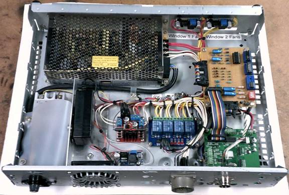
Appendix A – Schematic
Like many of my other home automation projects I used an old TiVo Series 2 chassis to house the electronics. A small 24V fan replaced the original 12V TiVo fan to provide cooling whenever the 24V supply is turned on.
The controller is positioned vertically under the window on what was the front of the TiVo. The plastic TiVo bezel was removed and I attached four rubber feet to that side of the chassis.


Appendix B – WebControl Configuration Pages
There are several web based configuration pages that determine system operation.
Network Setup
 This page selects DHCP or static configuration. It also allows setting
the NetBIOS name. Web access to the controller can be unrestricted or require
username/password login.
This page selects DHCP or static configuration. It also allows setting
the NetBIOS name. Web access to the controller can be unrestricted or require
username/password login.
WebControl time can be set automatically via NTP or manually. The controller does not have a built in battery backed real time clock, time must be set each time controller is powered up or it is set to firmware default date/time. I run my own LAN based NTP time server so point the controller at that time server rather than one on the Internet.
Pressing “Send” updates network settings and reboots the PLC. This is a handy way to reset the PLC remotely even when not making any changes to network settings.
I/O Setup
Individual outputs can be configured to allow PLC control and direct browser control. In most cases PLC code will eventually force the output to correct value even if web browser attempts to set or reset it. For critical outputs the browser interface can be disabled.
The active polarity of the outputs is set from this page.

Temperature Sensor Setup
18B20 1-wire temperature sensors are individually serialized. The controller detects attached temperature sensors at power up but they must be manually assigned to a particular sensor ID and units of measure specified.

Notify Setup
Email can be set up to use any TCP/IP port but the unit does not support SSL. In addition to email this page also configures HTTP GETs (not used in this example).
Up to eight email messages may be configured and each may be sent to a different email address. In addition to the user defined subject line and message body System Status page information is automatically appended.
 |
I noticed a problem setting message body text with some web browsers (Firefox, chrome, IE10) the second character of each line after the first is lost. Setting message body works fine using IE8.
Appendix C – WebControl PLC Code
Window Ventilator Controller
T. Schmidt
*********** Change Log *********************
6/15/2015 Reduced opening hysteresis to 1F in auto mode to speed up
window opening at night. South facing outside temp sensor takes
a long time too cool off.
5/30/2015 Installed pair of adjustable DC/DC buck converters, one for
each window. Running fans at lower voltage (18V) dramatically
reduced noise. Fan power consumption reduced to about 1/3
compared 24v, 6w vs 18W, with commensurate reduction of CFM.
Voltage change is transparent to software.
Solved problem of bad info in email notifications. Reduce size
of total email ASCII so text does not get cut off. This solved
the problem of corrupt output and temp data. Curiously WC
saved the extra data and did not complain about the size but it
must have corrupted something internally.
5/23/2015 Added Hysteresis to manual mode to prevent short cycling if
inside or outside temp is near minimum. Added delay for fan
high mode to turn on each pair separately to reduce current surge.
5/22/2015 Fan were pretty loud. Used EDPM weather stripping to create a
resilient mount between polycarbonate panel and fan body.
Added aluminum angle stiffener above the four fans.
Fans still fairly loud but drumming sound has been eliminated.
5/13/2015 Window actuator and fans installed. Added debug code to send
email each time window opens or closes. Firmware appears to
be operating properly, time will tell.
Window flexes if attempt to open when locked. Added code to
reclose window against stop if locked to reduce stress on glass.
5/10/2015 Changed automatic mode. UROM3 sets min outside temp (T1 same as
before) UROM4 sets inside threshold temp. When outside (T1) and
inside (T2) are 2F higher than UROM setpoints and inside exceeds
outside by 2F window opens. When inside equal/less than outside
or outside too low window closed.
In manual mode inside/outside temp tested for hard coded min
UROM3/4 values to force close. High temp not verified.
2/7/2015 Taped over PLC heartbeat LED, flashing was distracting at night.
Deleted soft reset code, easier to just hit Network update.
Added dummy Window 2 code to set VAR3 to no current.
1/28/2015 Mag reed closed position switch sensing too sloppy - replaced
with microswitch.
1/25/2015 Rewrote open/close code to take advantage of new actuator current
sensing.
9/4/2014 Changed OP amp to peak detector, increased gain to 40x from 10.
Actuator jam shuts down too quickly for WC to detect peak
current spike.
3/20/2014 Added pinch recovery
3/17/2014 Added actuator code
3/5/2014 Code complete for Window 1 except control of window actuator.
Waiting on delivery.
3/3/2014 Built dummy window test jig for code development.
2/28/2014 Code start
2/28/2014 Hardware complete
1/6/2014 Project start
*************** PCB Hardware/Firmware version ****************
Hardware: 2.2.2
Firmware: 3.2.17d
Customer loop executed every ~50ms (minimal test code) 65ms-ish (real code)
VAR and RAM initialized to 0 by system at power up
To reset PLC to power up state - update network settings (Send)
RAM location reset to 0 on code upload, VAR not affected
WebControl takes about 400ms to init I/O at power up
Per CAI Support Temp sensors take up to 2 sec to stabilize at power up
Email takes about 1.5 sec to send, no timeout if SMTP server does not respond
TTL inputs have 10k pulldown
Output buffers 10mA per output, 30mA total
A/D 10V full scale 10-bits
9V Power consumption (PS 9V @1A)
175ma PLC only (Live Ethernet serving web page)
215ma PLC and interface board
14ma 24v power control SSR
24V Power consumption (PS 24V @6.5A)
Idle
22ma Idle - DC/DC down converter, H-bridge, relay logic, chassis fan
(low speed) actuator and window fans off.
Fan current draw
620ma Rotron fan @24V 240CFM
780ma Papst fan @24V 240CFM
345ma Papst fan @18V
Actuator run time (unloaded)
27 seconds open
27 seconds close
Actuator run time (installed)
33 seconds open
33 seconds close
Open
80-100ma Start surge (very short)
90ma Run
90ma End of travel peak
>365ma Jam surge (very short)
10ma Full open idle current
Close
80-100ma Start surge (very short)
80ma Run
>421ma End of travel peak
>470ma Jam surge (very short)
10ma Full close idle current
Actuator A/D current sensing
.1 ohm Isens 100mv per amp
Opamp 40x gain (20x peak det, 2X buffer)
Single ended 5V
Peak detector saturates at 3.72V output into WC A/D
<.360v No connection (worst case 9mv offset 40x gain) (155mv typ)
>1.500v Open/close jam
Temperature rise
Ambient temp 72F, chassis vertical orientation, 24V off
24V PS heatsink 73F
Interface board 77F
Ambient temp 72F, chassis vertical orientation, 4 fans running
24V PS heatsink 87F
Interface board 75F
***************** I/O Defs **********************
Analog Inputs
-------------
AIP1 - Window 2 I sense (4V per amp, saturates at 3.7V)
AIP2 - Window 1 I sense (4V per amp, saturates at 3.7V)
AIP3 - 1/2 5 volt motor supply sense
Digital Inputs
--------------
IP1 - Window 1 close sw
IP2 - Window 2 close sw
IP3 - Rain Sensor (not installed)
IP4 -
IP5 -
IP6 -
IP7 -
IP8 -
Digital Outputs
---------------
OP1 - 24v power supply enable
OP2 - Window actuator close direction (high to close)
OP3 - /Window 2 actuator run
OP4 - /Window 1 actuator run
OP5 - Window 1 Fan group A
OP6 - Window 1 Fan group B
OP7 - Window 2 Fan group A
OP8 - Window 2 Fan group B
Temperature Sensors
-------------------
T1 - Outside
T2 - Inside
T3 - Chassis
T4 - Not used
T5 - Not used
T6 - Not used
T7 - Not Used
T8 - Not used
Temp Sensor status (1 = OK)
------------------
TS1
TS2
TS3
TS4
TS5
TS6
TS7
TS8
Humidity Sensor
---------------
H1 - Display only
Email message Identifiers
-------------------------
EM1 - Wakeup email at power up
EM2 -
EM3 - System Fault status code in VAR1 or VAR2/3 if actuator fault
EM4 - UROM setpoint out range
EM5 - UROM setpoint OK
EM6 -
EM7 - Window Close
EM8 - Window Open
Variables
--------
VAR1 - System Status:
0=Power up
1=Normal operation
2=24volt or 5volt motor power supply failure
3=Temp sensor fail
Temp sensor fail cleared automatically on status OK, other faults reboot.
VAR2 - Window 1 most recent open/close cycle status code
0= Nop
1= Successful operation
2= Jam - window recycled to start position
3= No actuator current
4= Window closed switch failure
5= Window locked (Open cycle only)
6= Unable to recover from jam
7= Operation took too long watchdog expired
VAR3 - Window 2 most recent open/close cycle status code (not installed)
0= Nop
1= Successful operation
2= Jam - window recycled to start position
3= No actuator current
4= Window closed switch failure
5= Window locked (Open cycle only)
6= Unable to recover from jam
7= Operation took too long watchdog expired
VAR4 -
VAR5 - Elapsed seconds counter during open/close cycle
VAR6 - actuator operating current
0 = no current
1 = normal run current
2 = Jam current
VAR7 - HWfail email sent flag, 0 normal, 1 email has been sent.
VAR8 - Sum of current UROM values
RAM
---
RAM1 - Scratch
RAM2 - UROM1/2 state cache during operation
RAM3 -
RAM4 -
RAM5 -
RAM6 -
RAM7 -
RAM8 - Actuator duty cycle flag, forces a 30 idle delay after use.
Web Settings
------------
UROM1 - Window 1 mode
0=close window
1=open no fan
2=open low fan
3=open hi fan
4=auto no fan
5=auto low fan
6=auto hi fan
UROM2 - Window 2 mode (same as window 1)
UROM3 - Minimum outside temp in auto mode to open (55-85F)
UROM4 - Inside temp open setpoint in auto mode (65-85F)
******************* Modules *******************************
PUINIT
Power up init, sets default reg values and cycles 24volt supply for go/nogo
test. 1/2 5V DC/DC down converter voltage measured by A/D. If that is OK
both it and 24v supply assumed to be OK. TVS limits fault voltage to <10V
to protect analog front end.
TSENSOR
Verifies T1-3 temp status flag. If fail delay 3seconds and try again. If bad
set VAR1 status to 3 indicating temp sensor failure. This is the only error
that clears itself automatically, all others need reboot.
UROMCHG
Sums all four UROM registers to detect change. When change occurs RANGECHK
verifies each value in range. Email sent whenever UROM value is changed
and also at power up if any are out of out of range. Change detection is a
simply a summation, will miss event if two values changed in same but
opposite values.
WINDOWx
Determines open/close operating mode for each window. Rain forces window
closed. In manual mode window closed if inside/outside temperature drops
mim acceptable UROM values.
CLOSEWx
Turns fans off at start of cycle.
High level routine to close window, WINxRUN does the heavy lifting in both
directions. If WINxRUN reports jam attempts to recover, does open, than
close. Updates VAR2/3 with status. During any error event EM3 sent. If
unable to recover from jam second EM3 sent with VAR2/3 status of 6.
OPENWx
Same as CLOSEWx except if jam, attempts to close, then open and close.
If cycle successful calls WINxFANS. If UROMx set to high both fans turned
on. If fans set to low current seconds since 1/1/2000 (CTS) used as pseudo
random number to toggle which pair of fans to turn on.
WINxRUN
Direction set by CLOSEWx/OPENWx. Time synchronized to current second, this
delays operation up to a minute but since this is normally an automatic
operation not a big deal. During first 5 seconds of operation verifies
actuator is running, sets VAR6 1. After 5 seconds, 1) detects jam, high
current sets VAR6 2, 2) Detects end of actuator travel, low current or 3)
excessive cycle time, watch dog timeout.
At end of cycle evaluates: run time, current detection, and window switch
position to set VAR2/3 completion status. If locked in open direction
reverses direction to reseat window in fully closed position to reduce
glass stress due to jam flexing. If close jam detected immediately
runs actuator in open direction for a few seconds to remove pressure on
obstruction.
PWRCHK
If none of the fans are turned on switches 24 volt supply off to save power.
If 24V supply is on voltage verified. Powerchk enforces a 30 second delay
to insure actuator duty cycle limit is not exceeded.
HWFAIL
If VAR1 is other than normal (1) hardware fail email sent. VAR7 is flag used
to send a single email. If temp sensors fail and recover VAR7 flag reset
automatically. All other errors require hardware reboot.
******************* Code *************************
START
CALLSUB PUINIT
CALLSUB TSENSOR
CALLSUB UROMCHG
CALLSUB WINDOW1
CALLSUB WINDOW2
CALLSUB PWRCHK
CALLSUB HWFAIL
END
PUINIT:
TSTNE VAR1 0
RET
EMAIL EM1
SET OP2 1
SET OP3 1
SET OP4 1
SET OP5 0
SET OP6 0
SET OP7 0
SET OP8 0
SET VAR1 1
SET VAR2 0
SET VAR3 0
SET VAR7 0
SET VAR8 UROM1
ADD UROM2 VAR8 VAR8
ADD UROM3 VAR8 VAR8
ADD UROM4 VAR8 VAR8
CALLSUB RANGECHK
BZ RANGEOK
EMAIL EM4
RANGEOK:
SET OP1 1
DELAY 3000
CALLSUB VOLTCHK
SET OP2 1
CALLSUB WIN1RUN
CALLSUB WIN2RUN
SET OP1 0
RET
TSENSOR:
TSTEQ VAR1 2
RET
AND TS1 TS2 RAM1
AND TS3 RAM1 RAM1
BZ BADSENSOR
GOODTEMP:
TSTNE VAR1 3
RET
SET VAR1 1
SET VAR7 0
RET
BADSENSOR:
DELAY 3000
AND TS1 TS2 RAM1
AND TS3 RAM1 RAM1
BNZ GOODTEMP
SET VAR1 3
RET
UROMCHG:
SET RAM1 UROM1
ADD UROM2 RAM1 RAM1
ADD UROM3 RAM1 RAM1
ADD UROM4 RAM1 RAM1
TSTEQ RAM1 VAR8
RET
SET VAR8 RAM1
CALLSUB CLOSEW1
CALLSUB CLOSEW2
CALLSUB RANGECHK
BZ UROMOK
EMAIL EM4
RET
UROMOK:
EMAIL EM5
RET
RANGECHK:
TSTLT UROM1 0
RET
TSTGT UROM1 6
RET
TSTLT UROM2 0
RET
TSTGT UROM2 6
RET
TSTLT UROM3 55
RET
TSTGT UROM3 85
RET
TSTLT UROM4 65
RET
TSTGT UROM4 85
RET
RET
WINDOW1:
TSTNE VAR1 1
RET
TSTEQ IP3 1
GOTO CLOSEW1
TSTLT T1 550
GOTO CLOSEW1
TSTLT T2 650
GOTO CLOSEW1
SET RAM2 UROM1
TSTGT RAM2 6
GOTO CLOSEW1
TSTEQ RAM2 0
GOTO CLOSEW1
TSTGT RAM2 3
GOTO WINDOW1A
TSTLE T1 570
RET
TSTLE T2 670
RET
GOTO OPENW1
WINDOW1A:
MUL UROM3 10 RAM1
TSTLT T1 RAM1
GOTO CLOSEW1
MUL UROM4 10 RAM1
TSTLT T2 RAM1
GOTO CLOSEW1
TSTLE T2 T1
GOTO CLOSEW1
ADD UROM3 1 RAM1
MUL RAM1 10 RAM1
TSTLT T1 RAM1
RET
ADD UROM4 1 RAM1
MUL RAM1 10 RAM1
TSTLT T2 RAM1
RET
ADD T1 10 RAM1
TSTGT T2 RAM1
GOTO OPENW1
RET
CLOSEW1:
SET OP5 0
SET OP6 0
TSTGT VAR2 1
RET
TSTEQ IP1 1
RET
EMAIL EM7
DELAY 3000
SET VAR2 0
SET OP2 1
CALLSUB WIN1RUN
TSTLE VAR2 1
RET
EMAIL EM3
DELAY 3000
TSTNE VAR2 2
RET
SET OP2 0
CALLSUB WIN1RUN
TSTGT VAR2 1
RET
SET OP2 1
CALLSUB WIN1RUN
TSTLE VAR2 1
RET
SET VAR2 6
EMAIL EM3
DELAY 3000
RET
OPENW1:
TSTGT VAR2 1
RET
TSTEQ IP1 0
RET
EMAIL EM8
DELAY 3000
SET VAR2 0
SET OP2 0
CALLSUB WIN1RUN
TSTLE VAR2 1
GOTO WIN1FANS
EMAIL EM3
DELAY 3000
TSTNE VAR2 2
RET
SET OP2 1
CALLSUB WIN1RUN
TSTGT VAR2 1
RET
SET OP2 0
CALLSUB WIN1RUN
TSTLE VAR2 1
GOTO WIN1FANS
SET OP2 1
CALLSUB WIN1RUN
SET VAR2 6
DELAY 3000
EMAIL EM3
RET
WIN1RUN:
SET OP1 1
SET RAM8 1
SET VAR6 0
SET VAR5 1
WIN1SYNC:
TSTNE CS 0
GOTO WIN1SYNC
SET OP4 0
DELAY 100
WIN1BGN:
TSTGT AIP2 20
SET VAR6 1
TSTNE CS VAR5
GOTO WIN1BGN
INC VAR5
TSTLT VAR5 5
GOTO WIN1BGN
WIN1OPR:
TSTGT AIP2 150
SET VAR6 2
TSTEQ VAR6 2
GOTO WIN1DONE
TSTLT AIP2 20
GOTO WIN1DONE
TSTNE CS VAR5
GOTO WIN1OPR
INC VAR5
TSTLT VAR5 45
GOTO WIN1OPR
WIN1DONE:
SET OP4 1
SET VAR2 3
TSTEQ VAR6 0
RET
SET VAR2 7
TSTEQ VAR5 45
RET
TSTEQ OP2 0
GOTO WIN1OPEN
SET VAR2 1
TSTEQ IP1 1
RET
SET OP2 0
SET OP4 0
DELAY 3000
SET OP4 1
SET VAR2 2
RET
WIN1OPEN:
SET VAR2 5
TSTEQ VAR5 5
GOTO WIN1LOCK
SET VAR2 2
TSTEQ VAR6 2
RET
SET VAR2 1
TSTEQ IP1 0
RET
SET VAR2 4
RET
WIN1LOCK:
SET OP2 1
SET OP4 0
DELAY 5000
SET OP4 1
RET
WIN1FANS:
TSTEQ RAM2 1
RET
TSTEQ RAM2 4
RET
TSTEQ RAM2 3
GOTO W1FANHI
TSTEQ RAM2 6
GOTO W1FANHI
ANDB CTS 1 OP5
XOR OP5 1 OP6
RET
W1FANHI:
SET OP5 1
DELAY 3000
SET OP6 1
RET
WINDOW2:
NOP
RET
OPENW2:
NOP
RET
CLOSEW2:
NOP
SET VAR3 3
RET
WIN2RUN:
NOP
SET VAR3 3
RET
PWRCHK:
TSTEQ RAM8 1
DELAY 30000
SET RAM8 0
TSTEQ OP1 1
CALLSUB VOLTCHK
CALLSUB SYSSTATUS
TSTEQ OP5 1
RET
TSTEQ OP6 1
RET
TSTEQ OP7 1
RET
TSTEQ OP8 1
RET
SET OP1 0
RET
SYSSTATUS:
TSTEQ VAR1 1
RET
SET OP5 0
SET OP6 0
SET OP7 0
SET OP8 0
RET
VOLTCHK:
TSTLT AIP3 225
GOTO VCHK2
TSTGT AIP3 275
GOTO VCHK2
RET
VCHK2:
DELAY 1000
TSTLT AIP3 225
SET VAR1 2
TSTGT AIP3 275
SET VAR1 2
RET
HWFAIL:
TSTEQ VAR1 1
RET
TSTEQ VAR7 1
RET
EMAIL EM3
DELAY 3000
SET VAR7 1
RET
******************* End **************************