|
Schmidt Consulting |
|
Portable Backup Generator |
|
|
|
|
|
Tom Schmidt |
|
1/11/2025 |
Originated 8/1/2016
|
Even though we live in a semi-rural area the electrical utility is pretty reliable but we are occasional victim of multiday outages, typically due to winter ice storms. Our house has a minisplit HVAC system but we also have the option of heating with cord wood so staying warm is not an issue. However we have a well so lose running water during an outage. I could not justify the cost of a whole house generator so opted for a small gasoline fueled portable generator. This paper discusses fuel choices and electrical wiring. Plus none of my projects would be complete without some electronics so I designed a simple generator status panel. |
Table of Contents
Removing Generator Neutral Ground Bond
Shut Down/Restart During an Outage
Overview
We live in a semi-rural area in New Hampshire. Overall electrical service has been very reliable. Most outages are due to severe ice storms in which case we, along with most of the state, can be without power for a week or more. We have a minisplit heatpump system but also have a cord wood stove so staying warm is not a serious problem. However we have a well so when we lose power we also lose running water. Luckily we have a nearby stream as a source of non-potable water for toilet flushing. But hauling water in five gallon buckets gets old fast. Our wood stove does double duty as a preheater for hot water so without electrical power we have to operate stove at a low level to prevent boiling water in the heat exchanger. In 2021 we were able to switch to fiber for internet and landline phone. Fiber requires local power so during an outage we lose both internet and landline phone. Our Cell phones will continue to work but we are in a weak signal area so they do not work at all locations within the house. An outage of a day is an adventure, but it gets old fast if it persists much longer.
Our solution was to purchase a portable 7 KW electric start gasoline generator in 2016 and install a generator interlock on our service entrance panel. I built a generator shed on the north side of the house to store the generator when not in use and protect it from rain and snow during an outage. A DIY generator status panel is located next to the circuit breaker panel to keep tabs on generator health.
Generator Sizing
As with any engineering problem sizing is a tradeoff, the larger the generator the less you have to manage electrical loads but it increases fuel consumption. Our electricity consumption is about 30 kWh a day, exclusive of domestic hot water (separately metered). If we assume the entire amount is consumed in 12 hours we have an average load of 2.5kW. Loading is highly variable so generator needs to be large enough to accommodate peak loads. During an outage we are not going to use high powered electrical devices reducing overall consumption. Extended outages normally occur during the winter so we will be able to use our wood stove for heat rather than the minisplit heat pump. In researching generators 7kW seems to be a common “largest” size and even somewhat lower wattage rated generators use the same size gas engine. The capacity of 10AWG wire protected by a 2-pole 30A circuit breaker is 7.2kW. A larger generator needs larger wire and connectors increasing cost. With a 7kW generator we should be able to run the electric dryer as long as we are not using any other high power appliance but have not actually had to do that yet. On balance 7 kW seems to be a good tradeoff between convenience, minimizing fuel consumption and cost.
Fuel Choices
This was a difficult decision. Residential generators commonly use: natural gas, diesel, propane or gasoline. Another issue is how much fuel to keep on hand and how difficult will it be to replenish fuel during an extended outage. I discarded the first two, as we are not connected to a natural gas pipeline and have no fuel oil appliances. That left propane or gasoline.
Propane’s advantage is long shelf life, it does not degrade like Ethanol gasoline blend. Most propane generators are designed to use small 20 or 30 pound gas grill cylinders. Propane, called LPG (liquefied petroleum gas) has the very useful property of becoming liquid at room temperature at modest pressure, several hundred pounds per square inch. Liquid being much denser than gas enables a lot of energy to be stored in a small volume. Propane delivery works because as gas is drawn off, pressure is reduced causing the liquid to boil converting more liquid to gas. The problem occurs when demand is high, tank is small and ambient temperature is low. Vaporization requires energy, causing tank temperature to drop. If it drops enough there is not enough gas being produced to operate the generator. Propane temperature dependency is not an issue in warm climates but here in frozen New Hampshire with winter temperatures below zero Fahrenheit it is a serious shortcoming.
We have a 100 gallon propane tank for our kitchen range. The large tank minimizes the effects of low temperature. Modifying our propane plumbing to accommodate a generator is a long term possibility but I opted not to spend the money at this time. If I decide to pursue that option there are dual fuel generators available or I can modify our generator with a propane adapter kit.
So the winner by default is ordinary gasoline. Gasoline is a less than ideal fuel for backup generator use. Storage is an issue as modern 10% Ethanol blend degrades rapidly. Using gas stabilizer extends storage life but it still has limited life expectancy so we need to rotate stock to keep the gas fresh. The generator is rated at 2 hours of run time per gallon at 50% load. As a back of the envelop calculation operating the generator for a couple of hours in the morning and three at night consumption will be about 2.5 gallons per day. I purchased five 5 gallon gas cans. Four of which are always kept full, the fifth is used for our lawnmower so is only partially full at any given time. That should provide enough fuel for a week long outage. During past outages power in the center of town was unaffected so getting replacement gas and more importantly coffee was not a problem. In the case of an extended outage where gas is hard to obtain we will need to husband our supply and run the generator fewer hours each day. To keep the gasoline fresh, as it gets old I put it in our cars and replace with fresh gas and stabilizer. So far we have not had a problem with year old gas but ideally strive for a 6-month replacement cycle.
The other electrical outages risks in our area are: traffic accidents, hurricanes and tornados. We are at the northern limit of Atlantic hurricanes so that risk is small. New Hampshire has had occasional severe bouts of tornado activity. While devastation in the tornado path is severe it tends to be localized, unlike ice storms. Traffic accidents occasionally take out a utility pole but again this is a localized problem with fairly rapid power restoration time.
Generator Selection
 Reviews of portable generators are all over the map.
With a gas generator the key to reliable operation is managing the fuel supply
so stale gas does not gum up the carburetor and to monitor oil level and
perform regular oil changes. Normally I shy away from Harbor Freight electrical
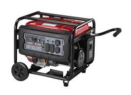
equipment but the 7KW running watts (8750 start) Predator non-inverter
generator had positive review by Consumer Reports and online customer reviews
are also generally favorable. The physical construction of the generator is
ideal for our purposes. The air intake is located towards the house and hot
exhaust is on the handle side. When looking at the generator from the handle
side the controls and receptacles are on the left.
Reviews of portable generators are all over the map.
With a gas generator the key to reliable operation is managing the fuel supply
so stale gas does not gum up the carburetor and to monitor oil level and
perform regular oil changes. Normally I shy away from Harbor Freight electrical
equipment but the 7KW running watts (8750 start) Predator non-inverter
generator had positive review by Consumer Reports and online customer reviews
are also generally favorable. The physical construction of the generator is
ideal for our purposes. The air intake is located towards the house and hot
exhaust is on the handle side. When looking at the generator from the handle
side the controls and receptacles are on the left.
![]() Since over a decade the generator may only see a few
hundred hours of operation I thought it was worth the risk. The generator has
electric start, in addition to manual recoil pull cord. Electric start is a
nice feature in the dead of winter and as I get more decrepit but requires
diligence to insure the battery is reliable after months of inactivity.
Since over a decade the generator may only see a few
hundred hours of operation I thought it was worth the risk. The generator has
electric start, in addition to manual recoil pull cord. Electric start is a
nice feature in the dead of winter and as I get more decrepit but requires
diligence to insure the battery is reliable after months of inactivity.
Electrical Considerations
When using a backup generator it must be prevented from feeding power back to the utility grid as this poses a hazard to power line workers. Generator grounding can be confusing since the configuration differs when the generator is used by itself (separately derived system) then when it is connected to a residence. Lastly electric start requires a small lead acid battery. The battery needs to be kept charged but undercharging or overcharging will cause premature failure.
Grounding and Bonding
This can be a confusing topic. In a nutshell the purpose of bonding is to insure any conductive metallic surface has a low enough resistance back to the power source so in the event of a fault there is enough current to trip the over current device. Grounding on the other hand bleeds off static charge and maintains the neutral conductor voltage near that of local Earth potential.
It takes very little current to produce a shock and only a little more to cause electrocution. These values are much smaller than the rating of a typical branch circuit breaker or fuse as shown in this chart:

Figure 2 Shock Values for the human body
So let’s see how that affects using a portable generator.

Figure 3 Generator Bonding and Grounding
The figure above is a standalone generator, termed a separately derived system, meaning it is not connected to any other electrical system. In this case if the motor has a fault to the frame the EGC (Equipment Grounding Conductor) aka green wire is able to carry enough current to trip the circuit breaker eliminating the shock hazard.
Ground fault detection works differently. If the generator is equipped with a GFCI (ground fault circuit interrupter) when leakage current exceeds 5 +/-1 ma (5 one thousand of an ampere) it will trip. The GFCI detects ground faults by measuring the current in the hot and neutral conductors. Ideally they should be identical. During a ground fault some current bypasses the neutral conductor creating an imbalance the GFCI detects. If a person is in contact with something electrified and there is a path back to the source this small current difference is detected and the GFCI trips deenergizing the circuit. Note this current imbalance is tiny and not enough to trip an ordinary circuit breaker.
The EGC and GFCI operate the same way regardless of whether they are used with a portable generator or in your residence powered by the utility company.
The neutral and EGC are both connected to the same point on the supply, why? Neutral is the current carrying conductor. The EGC’s purpose is to provide a separate low resistance path back to the supply so in the event of an ungrounded conductor fault the EGC is able to carry enough current to trip the overcurrent device (aka circuit breaker). The EGC is connected to neutral at one location and one location only. In a typical residence this is at the main circuit breaker load center.
Now let’s see what happens when we connect a portable generator to a home’s wiring. Remember the portable generator’s neutral is internally connected to the EGC that is required when it is functioning as a separately derived power source.
Thanks to Mike Holt for the following pictures.

Figure 4 Separately Derived System
Note the neutral and EGC are connected together at the Service Entrance and also within the generator. As mentioned there can only be a single connection between neutral and EGC. In this case we need to use a transfer switch that also switches neutral. That way at any given time there is only a single connection between the EGC and neutral.
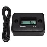
Figure 5 Non-separately Derived System
In a non-separately derived system the EGC to neutral bond is performed at the service entrance. They are kept separate at the generator. If the generator is always used for backup keeping the EGC and neutral separate is easy. Difficulty arises when using a portable generator. When connected to the residential electrical system neutral and EGC must be kept separate at the generator. If the generator is disconnected and used by itself it becomes a separately derived system. In that case the EGC and neutral need to be bonded within the generator for it to be used safely.
Mains Wiring
Insuring the generator cannot back feed the grid is critical. This can be accomplished by using a transfer panel or generator interlock. A transfer panel splits off circuits that are to be powered by the generator and provides A/B switching to select utility or generator. A generator interlock is a mechanical device that prevents the main and generator breaker from being on simultaneously. For new construction investigate feasibility of using a generator ready load center.
I opted for a generator interlock from GenInterlock as I did not want to replace our existing load center just for the sake of installing a generator. Using a generator interlock insures the generator cannot back feed the grid and provides a great deal of flexibility. During an outage as power use is limited only by the capacity of the generator.
Battery Charging
I wanted the convenience of electric start, didn’t want to have to depend on the recoil starter in the dark at -10F. The generator uses a small 10 AH SLA (sealed lead acid) battery for starting. Lead acid batteries are the Achilles heel of any electrical system. They have relatively short life expectancy of a few years and for a century old technology have pretty demanding charging requirements. For optimum life the battery needs to be kept fully charged to prevent sulfation with resultant loss of capacity but not overcharged resulting in excessive outgassing causing electrolyte loss. Over time all batteries self-discharge so for an application like this where the generator is only started every few months we need to use a battery maintainer to keep it fully charged but not over charged. Power Sonic has a nice SLA battery tutorial if you are interested in the gory details.
I chose to use a Deltran Battery Tender Junior. This is a smart 750 ma charger with a maintainer mode to keep the battery toped up without risk of overcharging.
 The charger has a multicolor LED indicating operating
mode:
The charger has a multicolor LED indicating operating
mode:
Flashing Red – unit powered but not connected to battery (or reverse polarity or battery voltage is extremely low)
Constant Red – battery is charging
Flashing Green – charged to ≥ 80%
Constant Green – fully charged, in battery maintenance mode
Generator Modifications
The generator does not come with wheels, handle or battery. I purchased the Harbor Freight wheel kit and 10 AH Thunderbolt Magnum SLA battery.
Not really a generator modification. The oil drain plug is located low in the engine. I use a small tinfoil container to hold drained oil. I purchased a long oil funnel to reach the fill port. Even though there is a dip stick on the fill port cap just add enough oil to reach the top of the fill port. By lucky happenstance the oil drain plug gasket for our Corollas fit the generator 12 MM drain plug.
Spark Plug
From my understanding the Predator engine is a Chinese clone of an older Honda engine. In reading reviews one of the things a lot of posters mentioned was to replace the original Chinese spark plug. Not sure why, at least in my case the engine works fine with the OEM Torch F6TC plug. But just to be on the safe I keep a NGK BP6ES on hand as a spare.
Runtime Meter
 Initially my intent was to use the multimode digital
meter on the generator status panel to log run time hours. Unfortunately that
turned out to be less than satisfactory, as it needs to be powered up to read
the time. I found a LCD runtime meter on eBay. It uses an inductive
pickup, a few turns of wire wrapped around the spark plug lead to detect engine
operation. It acuminates time in .1 hour (6 minute) increments. I attached it
to the generator with some double stick foam tape. The unit is completely
sealed, including the battery. Reading reviews it appears life expectancy is 3
years. Time will tell how long it lasts.
Initially my intent was to use the multimode digital
meter on the generator status panel to log run time hours. Unfortunately that
turned out to be less than satisfactory, as it needs to be powered up to read
the time. I found a LCD runtime meter on eBay. It uses an inductive
pickup, a few turns of wire wrapped around the spark plug lead to detect engine
operation. It acuminates time in .1 hour (6 minute) increments. I attached it
to the generator with some double stick foam tape. The unit is completely
sealed, including the battery. Reading reviews it appears life expectancy is 3
years. Time will tell how long it lasts.
Battery Charging
I attached a piece of EDPM weather strip to the battery hold down. This way I could tighten the hold down bolts with less risk of damaging the battery and hopefully dampening engine vibration.
The Battery Tender charging cord has an inline cable disconnect located near where it is attached to the battery. This allows the charger to be unplugged when relocating the generator. The Predator battery has unthreaded bolt on terminals. The ring terminals on the Battery Tender were too large so I crimped on smaller terminals. Having two connections on each battery post means the protective rubber boots no longer effectively cover the battery terminals so care is needed when working around the battery. The charger came with a 7.5 Amp ATO fuse, since it is only a 750 ma charger replaced it with a 5 Amp and keep a few spares in the shed just in case.
Removing Generator Neutral Ground Bond
Since the generator is normally connected to the house I removed the generator neutral ground jumper. In this particular generator it was located in the control panel. To provide provision to use the generator standalone I wired up a Twistlock plug with a neutral ground jumper to reestablish the bond. I added a warning label to the generator stating it has an isolated neutral.
Draining Excess Gas
When power is restored there may be a lot of gas remaining in the tank that should be drained. I had originally planned to add a tee to the gas line and an inline shutoff with a length of hose to drain the tank back into the gas can. Generator gas line plumbing is pretty tight so at least for the time being I plan to just run the generator out of gas and then shut off the fuel supply valve.
Status Panel
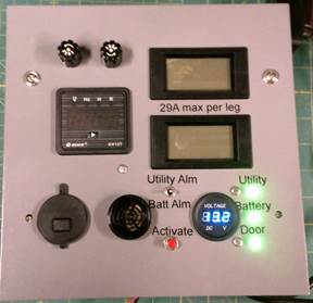
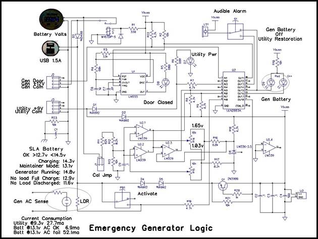
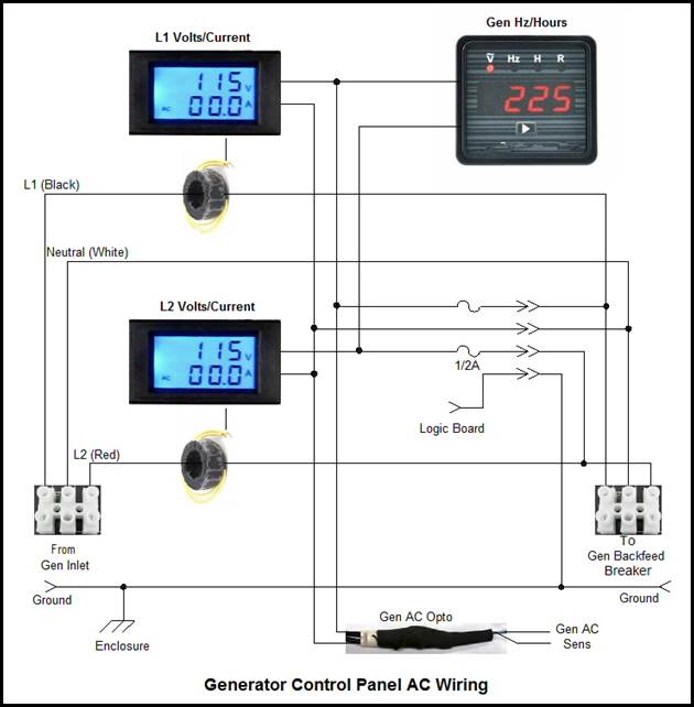
None of my projects would be complete without some form of electronics. The generator status panel is pretty simple. It has a digital AC voltage and current display for each 120V leg to monitor load balance and make sure we do not exceed generator current rating. The meters use a toroidal coil to provide non-contact current sensing. A third meter displays: volts, hertz, current run time and accumulated run time. The voltage reading is not all that useful as the other meters display the voltage of each leg. I use this meter to monitor AC frequency and runtime hours. The generator controls frequency by running the engine at a constant speed. This is critical as engine loading varies as the electrical load changes. Frequency is highest at no load and slowly drops as the load increases. So being able to monitor generator frequency is an important consideration. The display has two run time counters, one is reset each time power is lost and a second shows cumulative run time. The volatile run time counter makes it easy to monitor how long the generator has been on this cycle.
On the DC side I wanted to monitor battery voltage to make sure the charger and battery were healthy. I designed a simple window comparator using a LM339 comparator and LM336 2.5 volt reference. The battery LED is green if voltage is between 12.7 and 14.5V. It turns red outside this range and if the alarm switch is set an audible alarm sounds. A small DC voltmeter intended for motorcycles displays actual battery voltage. In the fully charged state the Battery Tender voltage is 13.0-13.1 V. When the generator is running battery voltage can exceed 14.5 volts so when running the generator need to turn off the audible alarm.
One of the problems using a generator interlock is determining when utility power is restored. The upper LED indicates utility power status. If the alarm switch is in the utility position an audible alarm sounds when utility power is active. Our utility meters electric water heater separately so that provided a convenient way to monitor utility power even with the main house breaker off. Where that is not the case an alternative detection method is to inductively monitor mains power using the same technique used by non-contact voltage detectors.
The bottom LED monitors the work light in the generator shed. When the door is closed the work light is off and indicator is constant green. When the generator door is opened an interlock switch automatically turns on the DC work light and the status indicator blinks. The generator battery is pretty small so if the work light is left on for an extended period during an outage when the generator is not running there may not be enough battery charge to start the generator.
At the lower left is a USB power outlet. It is designed for motorcycle use so it has a plastic protective cover over the switch and USB A receptacle. I wanted one with a switch so there was no idle power drain of the battery. This allows us to charge USB devices without the need to run the generator during an outage. It draws power from the generator battery so is adequate for charging cell phones without too much risk of excessively depleting the generator battery.
The pictures below were taken while I was debugging the unit. The one on the left shows the unit when utility power is active. The one on the right shows what it looks like when the generator is running during an outage.
|
Figure 8 Control Panel - Utility Power |
Figure 9 Control Panel - Generator Power |
The panel is powered from two different DC sources: 9 volts from a small SMPS attached to the electric water heater circuit and 12V from the generator battery. The 9 volt supply provides power to the logic circuits during normal operation. A disadvantage using a generator interlock is determining when power returns because the main circuit breaker has to remain off. Sourcing 9 volts from the separately metered water heater circuit proved to be an easy way to sense utility status even when the main breaker is off. The audible alarm generates an alert when utility power returns.
The circuit draws about 30ma from the 9 volt supply. When utility power is available the DC voltmeter is the only component powered by the generator battery. The battery maintainer easily makes up for this small draw keeping the battery fully charged.
When power is lost the panel is shutdown. I did not want to drain the generator battery during an outage. A pushbutton on the front panel turns the unit on to observe battery and door status when the generator is not running.
When the generator is running the unit automatically powers up. An optoisolator senses generator AC power and through a 2N3906 transistor powers the logic from the 12 volt generator battery. This way the unit only draws battery power when the generator is running. The optoisolator is simply a neon pilot light assembly coupled to a 5516 CdS light dependent resistor.
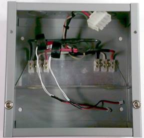
The unit is built into an 8”x8” Hoffman box. DC components are located at the bottom of the front panel, the AC panel meters are at the top. Each meter’s AC leg is protected by a small fuse. Generator AC power enters the enclosure bottom left flows through the toroidal current sensing transformers and out to the generator back feed breaker in the main breaker panel. An Aluminum angle bracket separates the AC from DC side.
The status panel is located to the left of the main breaker panel making it easy to monitor generator status.
|
Figure 10 Front Panel |
Figure 11 Enclosure Wiring |


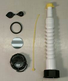
Figure 12 Status Panel DC logic
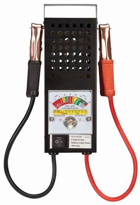
Figure 13 Status Panel AC
Generator Shed
One of the reasons I procrastinated getting a portable generator was deciding where to store it and how to protect it from the elements when in use. I decided to add a small bump out to the rear of the house. It is 3 feet deep and 12 feet long. A third is used for the generator and the rest for general garden tool storage. The shed is sealed off from the house; accessible only from the outside.
Shelves store dedicated generator supplies: such as oil and oil change tools, spare spark plug, 1,500 W electric heater used as a dummy load, fire extinguisher and operating instructions in case I’m not around.
Access Door
Instead of hinging the generator door on the side like a normal door I hinged it on top. When open the door becomes a makeshift roof. To access the generator need to unlatch and lift up the door. Attached to the bottom of the door are hinged legs. The legs are short sections of ¾” galvanized water pipe attached via floor flanges. The ends of the pipes are capped with rubber crutch tips to prevent them digging into the ground. Before I sided the door covered the sheathing with Grace Ice and Water Shield. That way if the generator needs to be left out in the rain or snow the door becomes a pretty serviceable roof. When closed the pipe legs rest on the shed floor.
In our area rain and snow typically come out of the west. I attached a tarp to the west side of the door to act as a wind break. Generator exhaust is towards to low side of the door so does not blow toward the tarp. For added protection there is an elastic bungee cord attached to the door jam and bottom of the door to tension the tarp. The section of tarp attached to the door jamb uses snap fasteners. These need to be undone when the monopole is used to increase door opening area.
The legs are pretty short so if I need to increase door open clearance unsnap the tarp from the door frame and use a longer pipe to act as a monopole. To prevent it from slipping out of position I drilled a counter sink hole in the hinged section of the door.
I modified a garage door lock kit to keep the door closed. I shortened the metal arms that normally go through holes in the door roller channel and routed slots in the door jamb to accept the locking arms. My homemade door is thicker than a typical overhead garage door so needed to add a bend to the locking bars to clear the door structure.
Ramps
The generator is heavy so I built the shed floor as low to the ground as feasible and built two detachable ramps. One is a two foot extension parallel to the floor. This allows the generator to be slid out into the door opening during operation. The other one is a sloped ramp that allows the generator to be removed and wheeled around. Aluminum angle brackets clip the ramps to the floor.
AC/DC Wiring
A flexible 4-conductor NEMA L14-30 twist lock 30A cord connects generator to the house generator inlet. A GFCI protected convenience receptacle powers the battery maintainer. The maintainer is wired to the generator battery, door interlock switch, LED work light and back to the generator status panel.
When the door is opened the DC LED work light is turned on. Nothing like working in the dark trying to start the generator. The interlock switch has a nifty feature that pulling the plunger out turns the light off. The status panel in the house monitors the light and flashes as a reminder when the light is on. The generator battery is pretty small and would soon become discharged if the light is left on without the generator running. The light is brighter then I needed so added a resistor to reduce power consumption.
In addition to the DC work light there is a normal mains power switched light.
I’ve installed thermal fire detectors at several locations in the house and outbuildings in addition to normal smoke and Carbon Monoxide alarms. I added thermal detector in the ceiling of the generator shed as protection against fire. The generator is hidden from casual view so I wanted to take every reasonable fire precaution.
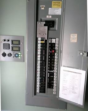
Figure 14 Generator Wiring
Fire Extinguisher
I keep a 3A, 40B-C fire extinguisher in the generator shed as a precaution.
Gas Can Modification
Gas is stored in five 5 gallon gas cans with stabilizer added each time they are filled. Modern gas cans are designed to prevent gasoline vapor from adding to air borne pollution. Due to their unvented nature and the complex spout arrangement gas pours very slowly and is pretty easy to spill. The last thing I wanted was to be outside spilling gas all over a hot generator.
Replacement Nozzle
I purchased a gas can modification kit. It consists of a replacement flexible nozzle and a traditional gas can vent. I drilled a ½” hole in each gas can and popped in the vent. This eases refueling, just attach the aftermarket nozzle and open the vent. The nozzle even came with a handy tie to prevent losing the screw on cap.
The gas can caps have a childproof plastic latch that must be depressed to unscrew the cap. This is hard to use in the cold so I cut it off.
|
Figure 15 Stock Nozzle |
Figure 16 Modifications |

DIY Gas Can Stopper
Much to my surprise modern plastic gas cans do not come with a stopper. As delivered the stock nozzle needs to be inserted into the gas when not in use to seal the can. I checked around but aftermarket gas can stoppers are few and far between and the ones I found were expensive. I found a source for polycarbonate disks on eBay. Polycarbonate is pretty resistant to gasoline. I measured the nozzle flange diameter and thickness and ordered a bunch. I removed the gasket from the stock nozzle and placed it around the disk. To prevent the disk from falling out of the cap used a little double sided foam tape to stick it to the inside of the cap, this is the part that is normally removed to insert the spout so is not exposed directly to the gas. So far my homemade stoppers are working well.
Gas Storage
When not in use gas is stored in a detached shed for safety. To track age each can is numbered and logged when gas is purchased. To simplify management gas is used sequentially. When gas can #3 is empty the next one used is #4 and so on. If we don’t use enough gas in yard tools to keep it fresh the old gas is transferred to our cars. I have not has problems storing gas in these sealed containers for a year but try to limit age to 6 months.
Finished Installation
The status panel is located to the left of the main service entrance. The generator interlock prevents the generator back feed breaker (top left) from being on if the main breaker is on.
I printed out circuit breaker directory and pasted it to the door and attached numbered labels next to each breaker. To keep things simple color coded the breaker number labels with a small colored dot. Green indicates breaker should be turned on when running on generator, red means leave off and no color is optional. The device located in slots 21/22 is a whole house surge protector.
Various caution labels came with the interlock kit. The one on the back feed breaker warns not to turn the breaker on if the front panel is removed. The ones above the main breaker to the right indicate where the generator is located and provides operating instruction.
Normally all thee generator panel indicators are green. The top indicates we have utility power. The middle that battery voltage is between 12.7 – 14.5 volts, exact voltage is available on the meter to the left. The bottom indicator is solid green indicating the generator work light is off. When the work light is on the indicator blinks. The AC meters at the top of the panel are off because the generator is not running.

Figure 17 Gen Status Panel and Main Breakers
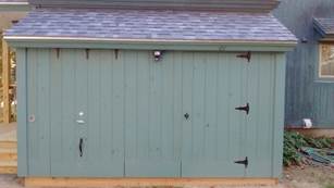
The generator bump out is located near the kitchen entrance at the rear of the house. The generator occupies a few feet on the left. Space on the right is used for garden supplies. We park our cars by the shed so the area is kept plowed during the winter and convenient to the house entrance.
|
Figure 18 Generator/Garden Shed |
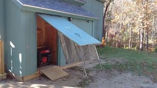
Figure 19 Generator Door Open |


Once the door is opened and the feet stabilized the platform extension is positioned in the opening and the generator slid out. The extension should be more or less level with the floor. If not a 2x6 is used to insure all the gas in the tank is used. If more access is needed the tarp is unsnapped from the door jamb and the longer pipe section propped under the door.
A loading ramp is used to move the generator in and out of the shed.
|
Figure 20 Generator In Operating Position |
Figure 21 Extended Door Opening |

Operating Instructions
In writing this up this description it seems harder and more complex than it is in actual practice.
Power Outage
1. Flip the generator alarm switch to utility. When power returns the audible alarm will sound. This also prevents the alarm from sounding due to high battery charge voltage when generator is running.
2. Open generator shed door and position legs that turns it into a roof. The door interlock switch automatically turns on the DC work light. Make sure west facing tarp is tight and all snaps fastened.
3. Position the generator floor extension ramp.
4. Stick the 2x6 shim on the ramp if it is not level to the floor. This insures all the gas in the tank will be used.
5. Extend generator handle.
6. Slide generator onto the ramp.
7. Connect the AC twist lock power cable to generator. The DC battery maintainer cable is always connected.
8. Add gas.
9. Open gas valve.
10. Set the engine choke.
11. Press the starter button. If that fails use the recoil pull starter or a jump battery.
12. Let the generator warm up and release the choke.
13. Pull out the work light door interlock switch plunger to turn it off.
14. Go back into the nice warm house and make sure voltage and frequency look good on the status panel. When the generator is running the status panel AC meters are active, even when the back feed breaker is off. Cycle through the readouts on the left hand meter to verify frequency is close to 60 Hz. Frequency should be about 61.5 Hz with no load and at least 58 Hz under heavy load. Maintain maximum load to less than 29 Amps per each 120 volt leg.
15. Open the breaker cabinet and turn off the main breaker and branch circuits.
16. Slide the generator interlock to the right.
17. Flip the generator back feed breaker on. Main breaker must be off to allow this.
18. Start turning on circuits starting with the highest power ones first: well pump and refrigerator. Do not turn on high current loads, marked with a black dot on breaker panel.
19. Make sure well pressure switch low pressure safety feature has not tripped. If so use the pressure switch manual override to run the pump to build up a little pressure.
20. Bask in the luxury of electric living.
21. CAUTION: Do not let generator run out of gas when powering the house.
Shut Down/Restart During an Outage
1. Turn off branch circuits to remove load on the generator.
2. At night push the door interlock plunger in to turn on work light.
3. Press the generator off button to stop the engine.
4. Let generator cool down.
5. Add gas as needed.
6. Set choke if engine is cold.
7. Restart generator.
8. Wait for it to stabilize.
9. Remove choke.
10. If the LED work light is on pull plunger out to turn it off.
11. Go back inside and turn on branch circuits.
Utility Power Returns
1. Assuming alarm switch is in utility mode the alarm sounds when power is restored.
2. Turn alarm switch off.
3. Wait a while to be sure utility power is stable.
4. Turn off branch circuits.
5. Turn off the generator back feed breaker.
6. Slide the generator interlock to the left so main breaker can be turned back on.
7. Turn on main breaker.
8. Turn on branch circuits.
9. Start the generator if needed.
10. Run generator until gas tank is empty. If there is a lot of gas in the tank plug in the 1500 W space heater to speed things up.
11. Switch off fuel valve.
12. Disconnect generator AC twist lock plug.
13. Perform any required maintenance, such as oil/sparkplug change.
14. Wait for the generator to cool off.
15. Slide generator back in and place ramp on top of the generator.
16. Release the generator handle.
17. Lift legs and close generator shed door.
18. Once battery voltage stabilizes flip the alarm switch to battery. This sounds the audible alarm if battery voltage is too high or low.
19. Make sure well pressure switch low pressure safety feature has not tripped. If so use the pressure switch manual override to run the pump to build up a little pressure.
20. Reset time on any non-battery backed up clocks.
21. Update generator usage log book.
22. Add stabilizer and refill gas cans.
Runtime cost
The generator datasheet indicates 2 hours per gallon at 50% load. So a gallon of gas produces 7 kWh of electricity. At $3.00 per gallon (Jan 2025 NH) that works out to $0.43 per kWh. That is about double our electric rate of $0.22 per kWh.
Periodic Testing
The generator should be run for 15 minutes or so every three months. This is a good time to visually inspect it and recycle any old gas into the cars. I use a 1,500 watt electric space heater to act as a dummy load when running the generator test.
1. Add a little gas. Use cans in numerical order, oldest gas first.
2. Turn on gas valve.
3. Set the choke.
4. Start the generator.
5. Let it warm up and remove the choke.
6. Plug in one or two 1,500 W heater(s) to the convenience outlets to load the generator. If only using one alternate which convenience outlet is used each time.
7. Run generator out of gas.
8. Turn off gas valve.
9. Update generator log book.
10. Add stabilizer and refill gas cans as needed.
11. At least annually change oil and check air filter.
12. Every once and awhile open carburetor float bowel drain to remove any water.
13. Every once and awhile do battery load test and log.
Monitoring Battery Capacity
The smart charger/maintainer does a good job maximizing battery life but lead acid batteries are the Achilles heel of any electronic project as they have relatively short life expectancy, under ideal conditions typically five years or so. I wanted to be able to periodically test the battery and replace it before it lost so much capacity to be useless in a backup situation.
There are lots of fancy battery load testers but I went with a simply old school unit with an analog volt meter and low value high power resistor that loads the battery at approximately 100 Amps. The 100 Amp specifications is rather lose because the device uses a resistive load that only draws 100 Amps at 12 volts. These testers have been around for years. I purchased mine from Harbor Freight.

Figure 22 Battery load tester
Using the tester is easy. Disconnect the battery maintainer. Connect the test clips to the battery terminals. The meter will indicate no load battery voltage. This should be between 12.8-13.2 volts for a fully charged battery. The open circuit voltage is affected by surface charge and varies some depending on how recently the battery was charged and to what voltage. Pressing the test button connects a low value high wattage resistor to the battery (.120 ohms). The meter shows the voltage drop. The higher the battery CCA (cold cranking amp) rating the smaller the voltage drop. When done disconnect load tester and reconnect battery maintainer.
The load tester displayed open circuit battery voltage of 13 volts. When I pressed the load button voltage dropped to 10 volts. I used a clamp on DC amp meter to measure load current of 82 amps. I was surprised the little 10 AH battery was able to deliver so much current. I’m not that concerned with the absolute value. I want to establish a base line and then every year or so recheck battery capacity. If the voltage under load begins to fall below the 10 volts I know the battery is losing capacity and should be replaced.
In early 2024 I replaced the battery with another one from Harbor Freight. The original battery was still able to start the generator without problems but was going on 8 years.
Parting thoughts
So far we have only had a single outage a couple of years ago when a wind storm knocked down several trees along our driveway. Power was out for a day and half. Personally if we never have another outage I’m still happy the house is equipped with a backup generator. Nice insurance and peace of mind. The entire project was not all that expensive costing just under $1200 (2016), not counting my labor or building the multipurpose shed.