|
Schmidt Consulting |
|
Long Range Mailbox Alert |
|
|
|
|
|
Tom Schmidt |
|
9/26/2022 |
http://www.tschmidt.com/
|
Our mailbox is on the far side of the road and the house is 600 feet away so off the shelf mailbox alerts do not have nearly enough range. I repurposed our retired muitipair outdoor telephone cable (we now have fiber internet) to provide the link between the mailbox receiver and house. A low cost RF key fob and receiver conveys mailbox status to a WebControl (PLC) programmable logic controller in the house providing visual and email notification when mail is delivered. |
Overview
This is a project I have been thinking about for a long time. Recently we were able to switch to fiber optic internet, making our existing outdoor copper telephone wiring redundant. Our house is about 600 feet from the road so none of the off the shelf mailbox alert devices have enough range. I bought an inexpensive 433 MHz RF key fob remote control transmitter and receiver on eBay and combined it with a WebControl8 PLC I have used for other home automation projects.
There are four main components of the system. A battery powered transmitter at the mailbox. Companion receiver located near the road and connected to the controller using the old multipair outdoor copper telephone cable. The controller consists of a WebControl8 PLC and a small board with interface electronics. Lastly a mail delivery status panel is located in the kitchen near the landline phone.
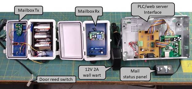
Figure 1 Mail Alert System
The system senses a change in mailbox door state to indicate when mail arrives. This addresses the situation where the door was not closed prior to mail delivery. When mail is delivered the mail status light turns green and the PLC sends a notification email. If the mailbox door remains open after mail is delivered the notification LED toggles between green and red indicating the door has been left open. Once mail is retrieved pressing the reset button on the status panel clears the alert and readies the system for additional deliveries during the day. The system knows the time so in the evening pending mail status is cleared. The following morning the state of the mailbox door is captured repeating the cycle waiting for the next delivery.
Remote Control Tx/Rx
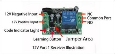
The wireless remote control function is built around a single channel 433MHz on/off key fob. The key fob emits a different code when the on and off buttons are pressed. These codes are processed by the nearby receiver and its output relay is latched to the most recent transmission.
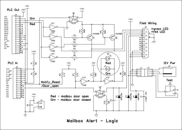
My goal was to transmit the on code when the mail box door is opened and an off code when it is closed. The PLC then uses this information to determine mail delivery. This turned out to be more difficult than I originally thought. The key fob transmitter uses a common RF 1527 encoder. The reference schematic shows the on/off buttons directly switching battery to activate the transmitter. Unfortunately the actual key fob circuitry was more complicated so I used a couple of optocouplers to simulate buttons being pressed. The next part of the problem was to convert the on/off contact of the mailbox door magnetic reed switch to pulse the appropriate button for a few hundred milliseconds. The switch contact is fed to a MOSFET to invert the logic level. The raw switch signal and MOSFET output are feed through small capacitors to generate triggers for the CMOS dual timer. The timer outputs in turn drive the appropriate optocoupler for about 300 ms simulating a button press.
The key fob was original powered by a 2032 Lithium 3V coin cell. The key fob itself only draws current when a button is pressed. However the circuitry I added needs to be constantly powered. I chose to use 3 1.5V Alkaline D batteries. This is overkill but I had a three cell holder in my junk box and D cells while having much more capacity then C cells cost about the same. The transmitter circuitry draws a constant 341 uA @4.5 V. During transmission this increases slightly however it is for such a short period and occurs so infrequently it can be ignored. 24/365 operation results in total consumption of 3 AH per year. An Alkaline D cell is rated at 15 AH down to .8 V terminal voltage. On the bench I verified the transmitter works down to 2.4V but I did not verify the impact of lower supply voltage on range.
The three D cell battery holder takes up almost all the interior rear of the enclosure. The key fob transmitter along with the extra circuity is built on a perf board. I did not want to drill holes in the door of the enclosure so used a strip of self-adhesive Velcro to attach the circuit board to the door.
The receiver additional circuity is much simplifier. It consists of TVS surge suppression diodes and bypass capacitors. In the on state (door open) the relay is energized sending +12V toward the house. In the off state (door closed) the relay is de-energized opening the circuit.
The transmitter, receiver and associated components are mounted in IP65 rated hinged door plastic enclosures. Plastic cable glands seal the boxes and the external cabling. This provides a waterproof home for the electronics.
With the system wired up and in their plastic enclosures I verified reliable signaling over 200 feet even behind trees and with my body blocking the direct line of sight between TX and Rx.
Transmitter Receiver Pairing
|
|
|

When a button is pressed the key fob transmits a 20 bit ID and 4 bit data word. A unique ID is hard coded into each transmitter allowing multiple transmitters to be distinguished from one another. The data bits specify which button was pressed. Note the transmitter does not implement rolling-codes for improved security. But for this application that is not a significant issue. The same ID code is always transmitted.
The receiver needs to be paired with each transmitter to properly respond to it and reject other transmissions. The pairing/learning method is unique to the receiver implementation. In our case the receiver has a three pin jumper to select the operating mode: Jog, self-lock, inter-lock and a pushbutton to pair it with the respective key fob transmitter. The mode is set to inter-lock, the key fob on button activate the receiver relay, off button turns it off. Some receivers are able to store the mode setting and dispense with the physical jumper.
The unit I purchased was already paired to both key fobs. Having two key fobs turned out to be handy during troubleshooting. Everything worked fine on the bench but when I installed the receiver near the road it responded correctly to the mailbox codes (door open/closed) however it was also turning on even without the mailbox transmitter being powered. I took the receiver back to the house cleared the pairings and had it relearn both key fobs. When I reinstalled the receiver the system worked correctly.
Pairing key fob transmitter(s) and resetting the receiver. Note: this is receiver implementation specific:
Ø Press and release the receiver learn button – indicator LED should pulse on to off
Ø Press any button on the remote. Indictor flashes indicating the remote is paired.
Ø To clear all learned remotes hold the learn button down for 8 seconds. Indicator pulses on to off indicating all paired remotes have been erased.
Mailbox
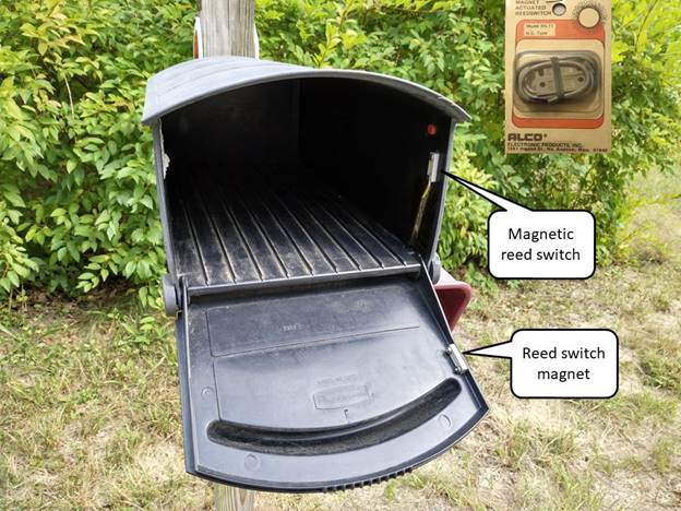
I was concerned about the door magnetic reed switch intruding excessively into the internal mail area. I had an Alco (now Augat) RS-11 reed switch on hand. The switch is much smaller than a typical screw terminal reed switch so is ideal for this application. I checked online and the switch is still available.
We have a Rubbermaid plastic rural mailbox. Finding the best location for the switch was surprisingly easy. The outgoing mail flag is located on the right hand side and its attachment pivot sticks into the right-hand wall a small amount (red button in photograph). I mounted the reed switch directly below and attached the magnet to the door stiffener flange. Switch and magnet are attached using 4-40 pan head screws. I drilled the screw holes slightly undersized to prevent rain ingress and filed the reed switch screws down to the nut to reduce the chance of snagging on the mail. The switch cable is passed through a hole in the floor and I secured it with a bit of Kapton tape. All in all modifying the mailbox was easier than I expected.
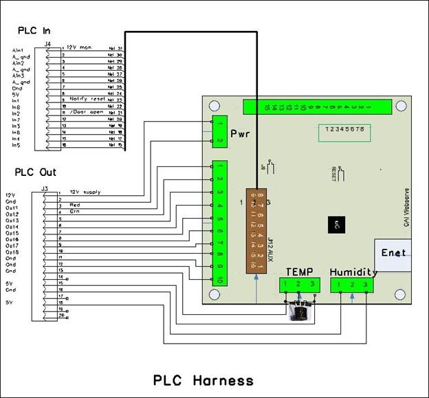
Controller
The heart of the system is a CAI networks WebControl8 PLC (programmable logic controller). I’ve used this PLC for several other home automation projects over the years. The unit has an Ethernet interface (only 10 Mbps but not an issue for our purposes) a built in web server and the ability to send email (however it does not support SSL email encryption). It also supports the Dallas 1-wire interface for temperature sensors and a Honeywell analog humidity sensor. Neither of which are used for the mailbox alert but I stuck in a Dallas DS18B20 1-wire temperature sensor as the control unit is located in the far corner of the basement so it provides an easy way to check temperature.
The interface board implements the circuity to drive and detect the mail status panel and read the output of the key fob receiver. I used an optocoupler to sense the receiver output. This provides a degree of surge protection due to the long external wiring. Better to blow up an optocoupler then the PLC.
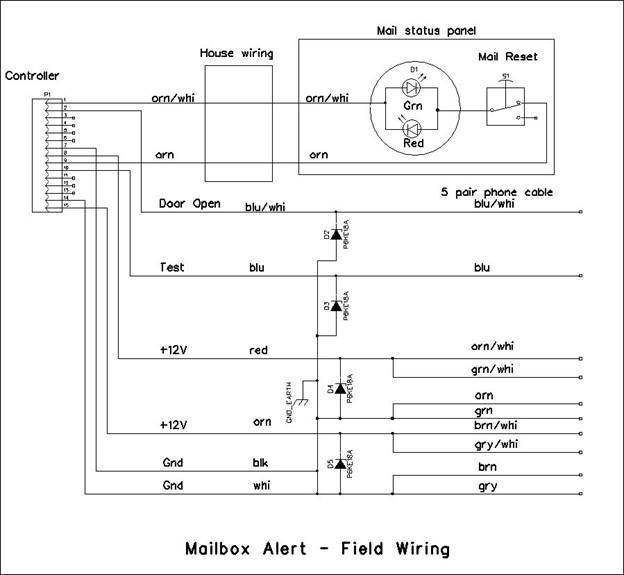
We still use a landline telephone only now it is implemented as VoIP by our fiber ISP. I wanted to locate the mail status panel near the kitchen landline telephone. The house is wired with two pair phone wiring. Since we only have a single landline I chose to use the second pair for the mail alert status panel. I wanted the status panel to provide mail delivery notification; indicate if the mailbox door was left open after mail delivery and reset the mail notification once mail has been retrieved. However I only had two wires to work with. I chose a bicolor red/green LED. These are two back to back LED diodes in a single package; the color is determined by lead polarity. To signal mail has been retrieved I wired a normally closed pushbutton in series with the LED. The PLC interprets no current in the LED circuit as the mail reset indication. To drive the bicolor LED I used an H-bridge. This is normally used to control motor forward and reverse direction so is ideal for this application.
The Ethernet interface is used by the PLC to obtain time and date information. The default URL is to use one of the internet pooled NTP servers. I run a NTP service on our poor man’s server so pointed the PLC to that resource. In the evening the PLC resets any pending mail alert. The next morning the PLC reads the current mailbox door state, either open or closed, and saves the information. When it detects a change in door state it assumes snail mail has been delivered. It then turns on the mail delivered LED and sends out an email notification. If the door remains open for an extended period it toggles the mail delivered LED between red and green indicating the mailbox door is open.
At power up and at each day/night and night/day transition the PLC performs a self-test. It verifies the 12V supply voltage is reasonable, it is able to initially access the NTP time server, that continuity exists to the mail alert panel and lastly the 1-wire temperature sensor is working as advertised. The self-test result is always sent during a power up but is only sent in case of a fault during day and night transitions.
A test button on the chassis sends 12V to the N.C. relay contact on the key fob receiver. A LED in the chassis monitors the receiver signal. With the mailbox door closed there is no voltage from the receiver relay so the LED is green. When the door is open or the test button is pressed the LED turns red. If the door is open pressing the test button has no effect. If pressing the test button changes mail box door status the controller reacts as if mail was delivered.
I used an old set-top-box chassis to mount the PLC and logic board. It is a smallish metal box with the top cover screwed into the rear panel. The system is powered by a 12V 2A wall wart. 2 amps is over kill but I chose it because the wall wart power cable has a large wire gauge reducing voltage drop under load.
Mail Annunciator
The key fob receiver came with a nice little plastic box that I repurposed as the mail status panel. I mounted the bicolor red/green LED and a normally closed pushbutton in the box and located it next to our landline phone in the kitchen.
When mail arrives the LED is illuminated green. If the mailbox door is left open the LED alternates between green and red. When mail is retrieved pressing the pushbutton resets the alert. This primes the system for another delivery in the rare instance that two occur on the same day. During the transition from day to night the controller clears pending mail notification readying the system for the next day.
Voltage Drop and Voltage Surges
A down side of using copper telephone cable is the small wire gauge. In our case the loop resistance is 24.8 ohms. This results in substantial voltage drop even with fairly low current consumption. Luckily our old outside telephone cable has 5 pairs of wires. One wire is needed to read the state of the key fob receiver relay and one for test. This leaves 4-pairs for power. Paralleling them reduces cabling resistance to 6.2 ohms. My intent is to eventually mount an illuminated LED street number sign above the receiver but so far have not purchased one. Even with the additional load of the LED sign voltage drop should not be a problem.
The other issue is transient voltage surges. Hundreds of feet of wire make a pretty good antenna. Where the telephone cable enters the house I bonded the DC power common to water pipe ground and used 18V TVS (transient voltage suppressor) diodes to clamp surges to 18V. For additional protection I used the same TVS diodes in the main chassis and at the receiver.
While the WebControl8 is able to send email using SMTP/POP log in credentials it is not able to perform SSL security encrypting the email message. Its big brother the WebContrl32 supports SSL but it is more expensive. Luckily I am still able to send unencrypted but authenticated email. However this is a limitation to be aware of as many ISPs require SSL. If you have a constantly on computer attached to your LAN there are email proxies that will accept non-encrypted email and output it as SSL but I have not tested or used any of them.
Email as Text Message
Depending on your Cellular carrier and phone you may be able to send email to your phone as a text message. This typically has the format of <YourPhoneNumber@carrier SMS gateway.TLD>
Cost
Like most of my projects this one consisted of raiding my junk box and purchasing new components. If everything is purchased new cost should be about $200 US in 2022 not including the telephone cable or mailbox itself.
Conclusion
This has been a fun project. Time will tell how well it will work in the depths of winter and the heat of summer.
Schematic


PLC Code
*********** Change Log *********************
9/24/2022 Now that the system is installed I increased open door timeout
to 25 seconds from 5. Have not seen spurious transition to on
state overnight.
9/23/2022 Used a 12V jump pack to power the receiver and learn the
Mailbox transmitter. Left receiver connected to jump pack no
mysterious switch to on state. Reinstalled the receiver in
weatherproof box. For good measure I added a .1 uf bypass cap
across the receiver 12V input. System seems to be working as
advertised.
9/22/2022 Removed the Rx module connected to 12V bench supply. Works fine.
Added 8 ohm series resistors on each leg, still working fine.
Cleared all learned remotes. Relearned spare remote on bench,
working fine. I will have to go out and learn the mailbox remote.
Fixed reversed polarity on orange twisted pair in basement.
9/21/2022 Installed mailbox transmitter and receiver. The TX works as
advertised able to turn Rx output on/off. Strangely the Rx output
goes on even without Tx and even when I removed Tx batteries.
Need to pull the Rx and test it on the bench. It had been working
on the bench for a week before I installed it.
The polarity on one of the twisted pair (orn) was revered. Telco
screwed up splicing the cable. I missed the wiring error so it
reduced voltage at the receiver to about 8V until I figured it out.
I doubt it did any damage, since voltage never went negative and
even it it did the TVS diodes in the receiver should have
protected it.
9/18/2022 Secured excess phone cable to utility pole at road.
Installed mag reed switch in mailbox.
Installed IP65 boxes at mailbox and utility pole.
Installed mail indicator in kitchen.
9/8/2022 Walked around yard to verify distance. Works reliably 200 ft even
behind trees and with me in between TX and RX. Have confidence
should work in real life. Distance between mailbox and receiver
is about 50 feet, hopefully mail jeep will not interfere with
propagation too much since it blocks line of sight during
transmission.
9/7/2022 Measured resistance of one pair of old phone cable: 24.8 ohms.
Cable is about 700 ft so this equates to 22 AWG conductors. Plan
is to parallel 4 pair for power reducing total resistance to 6.2 ohms.
Long term plan is to also install a lighted number sign above the
receiver. Need to determine how much current it draws to see how
much impact the high cable resistance will have. My guess is the
sign only draws 100-200 ma so cable resistance should not be a
problem.
9/6/2022 Hardware build complete and bench tested. Verified TX works down to
2.4V. Next step verify real world distance range in IP65 sealed
plastic box prior to install.
9/2/2022 I intended to use an old WebControl8 but the linear 5V regulator
was running at about 130F - 50F above ambient with a 12V supply.
Used newer rev 2.3.8 hardware with switch mode buck regulator.
Initial code build works as advertised. Enabled email but not text
and set door open timeout to 5 sec for testing
8/29/2022 Code start
8/26/2022 Finished building/debugging WebControl 8 PLC/kludge board control
unit and mail alert indicator module. I used an old set top box for the
main chassis.
8/8/2022 Old multipair phone line disconnected from street terminal freeing it
up to use for the mailbox alert.
1/6/2022 I ordered a single channel 433 MHZ on/off keyfob wireless remote control.
Verified it works at least 100 feet and mocked up circuitry to activate
buttons. The unit I have used more complex control then the reference
schematic, not just simple pulsing battery feed. Opted to use a couple of
opto isolaters to emulate the on/off push buttons and a dual one shot to
convert SPDT mag reed switch to pules. Waiting for old phone wire to be
freed up before I do serious construction.
*************** PCB Hardware/Firmware version ****************
Hardware: 2.3.8.
Firmware: 3.03.31
Static IP: 192.168.2.102
Customer loop executed every ~50ms (minimal test code)
VAR and RAM initialized to 0 by system at power up
To reset PLC to power up state - update network settings (Send)
RAM location reset to 0 on code upload, VAR not affected
WebControl takes about 400ms to init I/O at power up
Per CAI Support Temp sensors take up to 2 sec to stabilize at power up
Email takes about 1.5 sec to send, no timeout if SMTP server does not respond
TTL inputs have 10k pulldown
Output buffers 10mA per output, 30mA total
A/D 10V full scale 10-bits
12V power consumption:
Main unit: 90ma waiting new PLC hdw with buck regulator
Main unit: 100ma Mail received.
RC receiver <.1ua relay off 20ma relay energized.
TX power consumption 3 Alkaline D cells
341ua @ 4.5 V
245ua @ 2.5 V
Slightly higher during Tx but as this is so short is negligible.
Assuming battery voltage never decays this equates to 3AH per year.
Alkaline D cells are rated at 15AH down to terminal .8V so should
provide plenty of margin for annual change out. I could have almost
squeaked by with AA cells but I had the 3x D cell holder in my
stash.
***************** I/O Defs **********************
Analog Inputs
-------------
AIP1 - 1/2 12v supply voltage. Reads 621 with supply of 12.08V
AIP2 - not used
AIP3 - not used
Digital Inputs
--------------
IP1 - Notify reset PB - high no indicator LED current
IP2 - /Mailbox door open
IP3 - not used
IP4 - not used
IP5 - not used
IP6 - not used
IP7 - not used
IP8 - not used
Digital Outputs
---------------
OP1 - Green LED mail monitor
OP2 - Red LED mail monitor
OP3 - not used
OP4 - not used
OP5 - not used
OP6 - not used
OP7 - not used
OP8 - not used
Temperature Sensors
-------------------
T1 - Internal chassis Temperature
T2 - not used
T3 - not used
T4 - not used
T5 - not used
T6 - not used
T7 - not used
T8 - not used
Temp Sensor status (1 = OK)
------------------
TS1
TS2
TS3
TS4
TS5
TS6
TS7
TS8
Humidity Sensor
---------------
H1 - not used
Email message Identifiers
-------------------------
EM1 - Self test result - sent at power up and day & night transition if fault
EM2 - Mail arrived
EM3 - not used
EM4 - not used
EM5 - not used
EM6 - not used
EM7 - not used
EM8 - not used
Variables
--------
VAR1 - System Status: power up=0, normal operation 1, Supply volt out of tolerance
+/-10% 2, Unable to access NTP time server 3, Mail indicator module fault 4,
Temp sensor fail 5
VAR2 - Time of Day: night=0 day=1
VAR3 - Initial mailbox door status: closed=1 open=0
VAR4 - Mail state: waiting=0 arrived & door closed=1 arrived & door open=2
VAR5 -
VAR6 -
VAR7 -
VAR8 -
RAM
---
RAM1 - Scratch memory
RAM2 -
RAM3 -
RAM4 -
RAM5 -
RAM6 -
RAM7 -
RAM8 -
Web constants
------------
UROM1 - not used
UROM2 - not used
UROM3 - not used
UROM4 - not used
**************************************************
POST
Runs at power up. Delay for temp sensors to stabilize and sets VAR1
status flag =1 if all is well or error code if not.
Also runs at each day/night and night/day transition.
Email sent at power up and other times if fault detected.
DAYNIGHT
Mail status reset and mailbox door ignored at night transition.
At start of day VAR3 set with current door status, any change is
considered mail delivery. When mailbox door status changes VAR4 set
to mail active, green status indicator LED illuminated and notify email
sent. VAR2 set to 0 on night and 1 for day
When mail status is active, pressing the reset button on the status
indicator panel causes IP1 to go high. This resets indicator status, clears
VAR4 mail flag and resets VAR3 to initial door status in case there is a
second mail delivery during the day.
If door open for extended time VAR4 set =2 green/red status LED toggle at
1 sec interval.
******************* Code *************************
START
CALLSUB POST
CALLSUB DAYNIGHT
CALLSUB MAIL
END
POST:
TSTNE VAR1 0
RET
DELAY 3000
POST1:
SET RAM1 VAR1
SET VAR3 0
SET VAR4 0
SET VAR1 2
TSTLE AIP1 550
GOTO STERR
TSTGE AIP1 650
GOTO STERR
SET VAR1 3
TSTEQ CYEAR 2011
GOTO STERR
SET VAR1 4
SET OP1 1
DELAY 50
TSTEQ IP1 1
GOTO STERR
SET OP1 0
SET OP2 1
DELAY 50
TSTEQ IP1 1
GOTO STERR
SET OP2 0
SET VAR1 5
TSTNE TS1 1
GOTO STERR
SET VAR1 1
STERR:
SET OP1 0
SET OP2 0
TSTEQ RAM1 0
EMAIL EM1
TSTEQ RAM1 0
RET
TSTNE VAR1 1
EMAIL EM1
RET
DAYNIGHT:
TSTLE CH 7
GOTO NIGHT
TSTGE CH 19
GOTO NIGHT
TSTNE VAR2 1
CALLSUB POST1
TSTNE VAR2 1
SET VAR3 IP2
SET VAR2 1
TSTNE VAR4 0
RET
TSTEQ VAR3 IP2
RET
DELAY 100
TSTEQ VAR3 IP2
RET
SET VAR4 1
SET OP1 1
EMAIL EM2
RET
NIGHT:
TSTEQ VAR2 0
RET
CALLSUB POST1
SET VAR2 0
RET
MAIL:
TSTEQ VAR4 0
RET
TSTEQ IP1 1
GOTO RSTMAIL
TSTEQ IP2 1
GOTO DOORCSD
TSTNE IPINV2[25000] 1
GOTO DOORCSD
SET VAR4 2
TSTEQ OP2 1
GOTO RED
TSTEQ OP1[1000] 1
GOTO RED
RET
RED:
SET OP1 0
SET OP2 1
TSTEQ OP2[1000] 1
GOTO GRN1
RET
GRN1:
SET OP2 0
SET OP1 1
RET
RSTMAIL:
SET VAR4 0
SET VAR3 IP2
SET OP1 0
SET OP2 0
RET
DOORCSD:
SET VAR4 1
SET OP2 0
SET OP1 1
RET
******************* End **************************
This page intentionally blank