|
Schmidt Consulting |
|
12V Outdoor Lighting System |
|
Better Living Through LEDs |
|
|
|
Tom Schmidt |
|
3/22/2015 |
|
I wanted to improve our outdoor lighting and expand coverage to more of the yard. I selected 12V DC LED floodlights and PIR sensors in combination with a custom designed master controller in the house and a slave controller in garden shed to provide flexible control. |
Contents
LED Constant Current Driver Modification
Overview
We live in a rural area and I wanted to improve our outdoor lighting while reducing energy consumption. The existing lighting was a combination of line voltage incandescent and CFL fixtures. There were three main design goals: automatic parking space lighting when leaving and returning home, improve yard lighting when walking the dog, and create path lighting to compost bin.
The design uses 5 10W 12V LED floodlights, 4 outdoor and 1 indoor PIR sensors, and reworked 3-way switches to add a third yard light switch at the kitchen door. LED floodlights are installed at the house, on a small shed across the driveway adjacent to the house and on a utility pole a couple of hundred feet in front of the house. Signaling between the house and shed is over small gauge low voltage cable that would have too much voltage drop if used to power the lights directly. The shed has AC power so I designed the system with a master controller in the house and a slave controller in the shed.
Feature Set
Parking Area Lighting
We have two parking areas one behind the house the other behind the garden shed across the driveway adjacent to the house. I wanted to be able to use either area and have the lights turn on when leaving the house and when returning home. In addition if you are doing something near one of the parking spaces wanted the light to stay on for the duration.
A PIR sensor mounted near the kitchen door turns the lights on when leaving the house and an outdoor PIR sensor located on the utility pole a couple of hundred feet in front of the house turns the lights on when it detects a car coming down the driveway. Each of the parking area floodlights includes a PIR sensor. This keeps the respective light lit when it detects activity near the car.
A low voltage switch located by the kitchen door allows the parking lights to be turned on regardless of the state of the PIRs.
Yard Lighting
The house faces south and the bulk of the yard area, an acre or so, is in front. When we built the house installed an incandescent floodlight to illuminate the yard and another light on the west wall to illuminate the deck. The lights are controlled by two 3-way switches located near the basement and first floor doors. This turned out to be a less than optimal arrangement. When walking the dog we use the kitchen door at the back of the house so turning on the yard light is inconvenient.
The other shortcoming of the existing lighting scheme is it gets pretty dark the further you are away from the house.
Utility Pole Light
To increase the amount of yard illuminated I installed a 12V 10W LED flood light on the same utility pole used to locate the parking light PIR sensor. This adds fill in light to yard area far away from the house.
Because the utility pole yard light is so far away voltage drop is a problem, even using relatively large gauge cable. To reduce voltage drop I tied the common leg of PIR and light cables together at the pole. This doubles the effective size of the common conductor. The controllers’ use 12V power supplies and the LED modules are rated at 12 volts. I added a small DC/DC boost supply to increase the 12V to 15V to compensate for yard light voltage drop. The other LED lights operate from the normal 12V supply; the boost supply is only used for the pole light.
Multiple Control Locations
I wanted to add a third yard light switch by the kitchen door. Since there were already two 3-way switches adding a third normally entails using a 4-way switch and a multiconductor line voltage cable between the two existing switches. Rather than go that route I used the two existing switches and converted them to low voltage signaling via optoisolators. The optoisolators provide switch state logic input to the main controller. I could not simply convert the existing 3-way switches to low voltage since they shared a box with line voltage switching and there was no provision for an insulated divider. A new LV switch near the kitchen door provides the third switch input. To simulate a multi switch arrangement one pole of each of the existing 3-way switches feed an opto to convert it to a DC signal. These two inputs along with the new kitchen door switch are feed into a three level XOR chain. The XOR gates emulate the legacy 3-way switching. The output of the XOR chain drives a relay channel to control the utility pole mounted yard LED floodlight and a second output drives a SSR to control existing line voltage yard and deck lighting.
Compost Bin Path Lighting
We recycle and compost as much as possible. The compost bins are located at the far side of the shed so in years past it meant walking in the dark. I installed another LED flood light and PIR sensor high on the far wall of the shed. It illuminates the compost bins when it detects motion.
Shed Exterior Lighting
In addition to the parking and compost shed lights a third LED floodlight is located on the south wall of the shed to illuminate the garden. This light does not have a PIR sensor. The three shed lights have override switches in the shed to turn them on continuously if desired. These are low voltage switches and are processed by the shed controller.
Kitchen Door Switches
Three switches near the kitchen door control: 1) parking area lights 2) shed garden light and 3) yard lights. These are low switches are and processed by the house controller.
Day/Night Control
To minimize energy consumption we use a photo electric sensor to turn off the outdoor lights during the day. This controls power to the AC powered lights directly and supplies power to the main lighting controller located in the house.
An additional benefit of this arrangement is that if for any reason one of the PIR sensors hangs it gets a power cycle every day.
Controllers
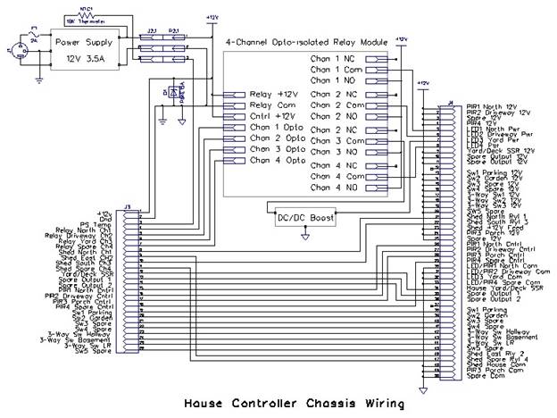
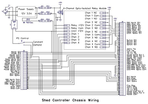
The system uses two controllers, the main controller is in the house and the slave is in the shed. This was necessitated by the small gauge cable connecting the house and shed. I designed in as much commonality as possibility to reduce the number of spare parts needed to maintain the system. Both are powered by a 12V 3.5A switching power supply, and use a 4 channel optically isolated relay module.
The chassis for both controllers are old TiVo Series 2 DVRs. I have used them for several other projects. They are a good size for this type of project and unlike other consumer AV gear removing the front plastic bezel yields a sold metal front panel. At the rear is a small 12V fan. I figured the fan was over kill but I wired up a simple temperature controller by clipping a PTC to the power supply heat sink to control the fan if the power supply gets too hot. The fan is the only electrical component I was able to salvage from the original TiVo’s.
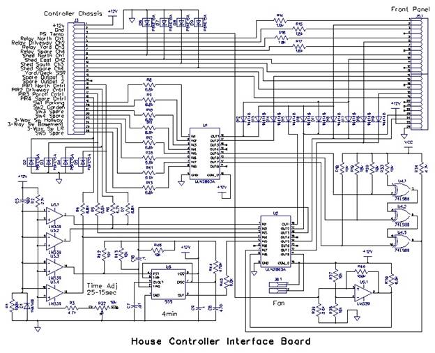
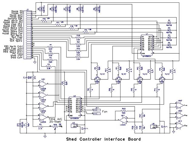
The controllers are simple discrete logic, no microprocessors are used. Each controller implements three stages: 1) input conditioning 2) diode OR gating 3) output power switching.
House Controller
The house controller functions as the master. Switched power from the day/night photocell automatically turns the unit on at dusk and off at daybreak. The LED floodlights lights are controlled by a 4 channel optically isolated 12V relay board. In the current implementation only two channels are used, one for the house parking light and one for the yard light. The house unit did not need to be optically isolated but it allowed me to use the same relay module in the shed controller. There are two SSR outputs, currently only one is used to control AC yard lighting.
Control inputs consist of physical switches, optoisolator outputs from the two existing 3-way switches and PIR outputs. Input are all high side switching, on is represented by the presence of 12V, off by an open circuit.
8-channel ULN2803A Darlington transistor arrays are used to invert the inputs and provide active low output drive for the relay module and SSR. These are nominally 5V input devices. Using 5V inputs in a 12V systems provides plenty of compliance when driven by diode OR logic. I added series input resistors to reduce array input current to what it would have been if feed by 5V.
The PIRs momentarily turn on at power up. To inhibit extraneous turn on at power up each of the four PIR input channels is clamped to ground up by a LM339 comparator driven by a simple RC network.
The house PIR sensor I used was intended as an intrusion detector, not a light controller. As such the output goes active only when it detects motion but there is no built in delay timer. To address that used a LM555 timer to provide about 4 minutes of on time when leaving the house. Unlike the other PIR sensors when first turned on it goes active for a long time. The 555 time is AC coupled so it only responds to a new detection. During the power up delay the 555 is held in reset.
As mentioned in the overview an XOR chain is used to simulate 3-way switching of the three yard light switches.
The inverting Darlington array converts the 12V active high input to an active low output that is able to directly drive the active low relay/SSR inputs. Diode steering is used to allow flexible output control. Diodes are connected between input functions and chosen outputs. This allows any combination of inputs to control any output without creating mutual interference.
Front Panel
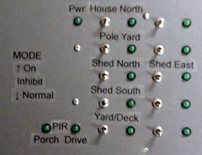 |
To facilitate debug the front panel has an LED indicator for each output and a 3-postion center off toggle switch. In the down position the respective light operates normally. In the center position it is off and the up position on.
Figure 1 House Controller Front Panel
The shed lights do not operate in exactly the same manner as separating input from output would have required more interconnect wiring than I had available. The off position only inhibits control from the master controller. If one of the shed switches or PIR sensors are on the light will remain on even though the house controller switch in the off position.
Status indicators for the porch and driveway PIR sensors to facilitate troubleshooting spurious turn on events.
Note: not all channels are currently being used. System design supports 4-DC lighting channels for the shed and 4-DC and 2-SSR channels for the house. Three channels are used in the shed and 2-DC and 1-SSR in the house.
Shed Controller
The shed controller uses the same power supply, relay board, and Darlington transistor arrays as the house controller. Due to the small gauge wiring between house and shed is not feasible to power the LEDs directly. The house controller provides 12V DC and 4 control signals to the shed. A SSR in the shed controller is used to switch the 12V power supply. There are two power control options: constant and demand. In constant mode the shed supply is on whenever the house controller is on. In demand mode the supply it only turned on if one or more of the lights are commanded on.
The shed is about 100 feet away from the house so I wanted to maintain metallic isolation between the house control circuit and shed DC power. The relay board opto inputs are powered by the house supply while the relays, PIR, and LEDs are powered by the shed 12V supply. Three switches, located by the shed door are also powered by the house supply. These allow manual override of automatic control.
The PIR outputs are conditioned in a similar fashion as the house controller through the inverting Darlington arrays and clamped at power up. An opto isolator connects each of the PIR outputs to the associated house referenced relay board opto inputs maintaining metallic isolation between the house and shed DC supplies.
Floodlight Modification
As received the LED floodlight PIR sensor is wired internally and is not available externally. In addition at 12V DC the input voltage is marginal. The LED array consists of a 3X3 matrix of white LED chips each with a forward voltage about 3.3v. A constant current driver interfaces the LED to the 12V DC source. For flexibility the constant current driver includes an input full wave diode bridge. This has the advantage of being able to power the module from AC or DC but has the disadvantage of adding significant losses due to diode forward voltage drop.
|
|
|
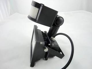
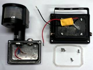
Figure 2 Modified PIR Floodlight
LED Constant Current Driver Modification
The floodlight came with different style LED constant current drivers; some were just bare PCBs other were sealed modules. I purchased some additional 12V 10W constant current sources as they were easier to rework then the ones that came with the lights. I removed the diode bridge and for protection added a 15V TVS diode across the inputs. To insulate the module added heat shrink over the PCB.
The modification also included separating the PIR output so it could be routed to the controller. The PIR/floodlight now has a 4-wire interface. 12V LED power, LED/PIR common, PIR power, PIR output.
|
|
|
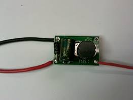
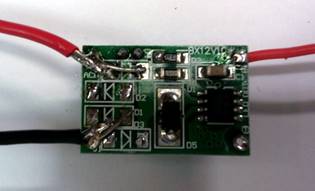
Figure 3 Modified LED Constant Current Drivers
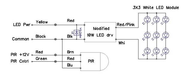
Figure 4 Floodlight Wiring Modification
Power Line Optoisolator
To interface the yard switches to low voltage DC I built my own opto isolator consisting of a 120V neon pilot light assembly and a GL5516 Cds photoresistor. When exposed to light the Cds resistance drops to a very low value. The off state is greater than 500k ohms and when illuminated by the neon light drops to about 1k.
Cds cell is heat shrunk to the front of the pilot light preventing entry of extraneous light.
|
|
|
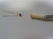
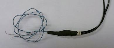
Figure 5 AC Optoisolator
Installation
This project, while simple electronically, was actually fairly large in scope. I had to completely replace the existing shed exterior lighting, add LV lighting and switches at the house and modify the existing yard lighting control method, not to mention running cable to the utility pole 200 feet in front of the house.
Utility Pole Wiring
The house is about 600 feet off the road; utility construction is aerial for the first 400 feet and then underground the final 200. When we built the house I dropped a 1” polyethylene flexible pipe into the trench between house and last utility pole. I had no idea as to the condition of the pipe after all these years. The first order of business was to see if it was possible to use the pipe. If not, I would be unable to implement most of the planned features as I was not about to dig another trench to bury the wire.
As an experiment I inflated a small balloon, stuck it in the pipe and used compressed air to see if I could get it all the way to the other end. To my pleasant surprise the balloon it popped out the far end. Next I cobbled together a blowing jig with a small hole for the pull string so I could use compressed air to force a balloon, now attached to a pull string through the pipe. Once again I used compressed air to force the balloon through the pipe. Now that I had a small pull string tied it off to ¼” nylon rope and pulled the larger pull rope through the pipe.
The plan was to pull two 4-conductor cables and a pull string, one of the cables feeds the yard light, the other the driveway PIR sensor. At the utility pole jury rigged a pulling rig consisting of a small L bracket screwed to the post, a dual pulley for the two cables and a pull string dispenser. Having a pull string in the pipe would eliminate the need to remove (hopefully) the two cables already in place if I ever need to add more cable.
Securely attached the cables and pull string to the pull rope and started pulling. I was doing this by myself so periodically went outside to see how things were going. Much to my delight pulling the cable turned out to be easier than I expected. With this critical first step complete it was time to design the controllers and install the rest of the system.
The pictures below show the cable pulling arrangement and the final PIR and light installation at the utility pole. The yard floodlight is on the left side of the pole at the same level as the weather head. I slid a section of 1-1/4” PVC conduit over the 1” pipe to provide slack to accommodate Earth movement due to winter freezing.
|
|
|
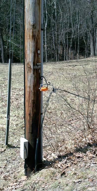
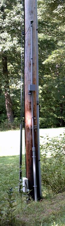
Figure 6 Utility Pole Wiring
Installing Floodlights
I installed the modified constant current drivers and in most cases prewired the lights with 4-conductor cable. This eliminated the need to splice the wires and attach the back of the floodlight from a ladder. As shown in the light modification picture the PIR leads are pretty short. At locations where I was only using the floodlight, no PIR, I still used 4-conductor cable in case I ever wanted to add a PIR later.
House Controller
The house controller is located in the basement near where underground wiring from the shed and utility pole enters the building. I installed a new receptacle, connected to the photocell, to provide power to the controller.
At both the house and shed used Telco Type 66-blocks to interconnect wiring. At the house used a 25-pair connector to allow easy disconnect of the controller in case I ever wanted to modify it. The controller cable is punched down to a 66-block. Additional 66-blocks terminate exterior wiring and lighting and switch wiring. This provides a great deal of flexibility to make changes and add additional lights. Cross connect wire (an old Telco term) is used to interconnect the house controller to inputs and outputs. The connector and cross connect wire gauge is small but it pretty short so does not significantly affect voltage drop.
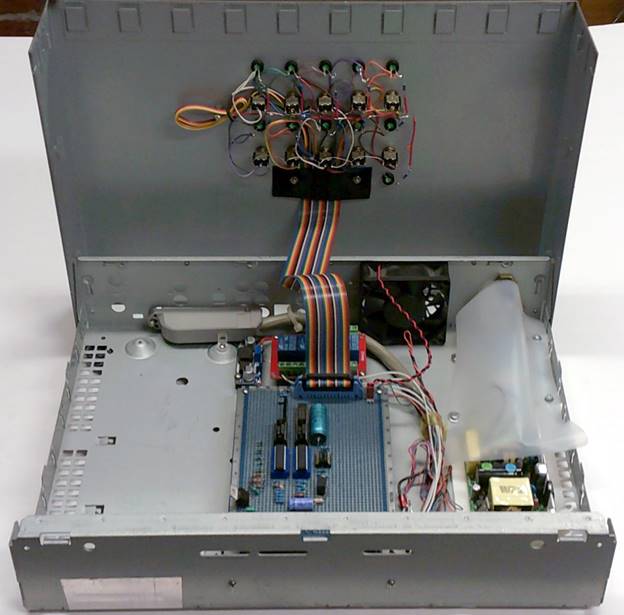
Figure 7 House Controller

Figure 8 House Controller Rear Panel

Modifying AC Yard lighting
I left this part of the project to the last. Luckily the wiring for the exterior yard light was accessible. Ran a multiconductor cable from the controller and installed a new square box to contain the SSR and two optocouplers.
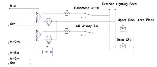
Figure 9 AC Yard Light Remote Control
Shed Controller
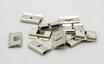
The slave controller is located in the shed attic. I thought it would be easier to make the connections if the 66-block was located within the controller. Type 66-blocks have four terminals in a row. In a normal configuration all four terminals are interconnected. In a split block the left pair is isolated from the right hand pair. Split blocks double the number of connections or with a bridging clip allow disconnecting left side from right side
 In this case
rather than using the split block to double the number of connections a
bridging clip is used to connect the left and right hand side. This facilitates
trouble shooting. Removing the bridging clip isolates that particular signal.
In this case
rather than using the split block to double the number of connections a
bridging clip is used to connect the left and right hand side. This facilitates
trouble shooting. Removing the bridging clip isolates that particular signal.
![]() The Constant/Demand switch is located on
the rear panel.
The Constant/Demand switch is located on
the rear panel.

Figure 11 Shed Controller
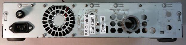
Figure 12 Shed Controller Rear Panel
Conclusion
All in all a fun project.
The system addresses a number of long standing short comings of the original outdoor lighting.