|
Schmidt Consulting |
|
DIY Weather Station |
|
|
|
|
|
Tom Schmidt |
|
3/15/2025 |
Originated 12/15/2019
|
This is another WebControl 8 project. It provides real time reporting of outdoor temperature, humidity, wind direction and wind speed as well as min/max temperature for the previous day. It uses recycled Davis Instruments Weather Station components. |
Overview
We were using a Davis Instruments Weather Monitor II and Ambient Weather Virtual Weather Station software to view local weather conditions on our LAN. The software was not happy when I switched to Windows 10.
I’ve had good luck monitoring temperature and humidity using the WebControl 8 PLC (programmable logic controller) for various projects. I decided to use one to create a personal weather station and make the data available on our internal network as a web page. That way weather information is accessible to any device on our LAN. For security reasons the information is not remotely accessible but if I ever need remote access I can set up a VPN or post it to a cloud service.
Real Time Temperature and Humidity

 For real time outdoor and indoor temperature and humidity
monitoring I purchased several ThermPro TP-60 wireless units. They have been
very accurate and are pretty cheap. I installed a single transmitter in the
weather station radiation shield for accurate reporting and located several
display units around the house.
For real time outdoor and indoor temperature and humidity
monitoring I purchased several ThermPro TP-60 wireless units. They have been
very accurate and are pretty cheap. I installed a single transmitter in the
weather station radiation shield for accurate reporting and located several
display units around the house.
A downside of the TP-60 is lack of easy access to min/max temperature logging and of course you have to go to one to view temperature and humidity.
I’ve used a bunch of WebControl 8 PLCs for other home automation projects so decided to use one as the basis of the weather station. Unlike my other projects it does not require any additional electronics so I was able to use the little WebControl chassis to house the controller. Both used to be available on eBay but in checking the WebControl 8 is only available on Amazon now and I could not find a source for the little chassis.
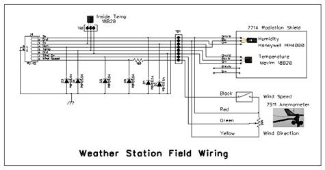
The PLC supports up to eight Analog Devices DS18B20 1-Wire temperature sensors and a single Honeywell HIH 4000 analog humidity sensor. The Weather Monitor II outdoor humidity module was pretty expensive and did not seem to be very reliable. Ours did not have one so this implementation is actually a functional improvement. The CAI Networks PLC has gone through multiple revisions over the years. Current production uses a switch mode buck power converter whereas early hardware used a linear regulator and an additional I/O connector was added. The temperature and humidity sensors are located in a Davis 7714 Radiation Shield as well as the TP-60 transmitter. A second temperature sensor is located on the surge protector PCB to report indoor temperature.
Wind Speed and Direction
Initially I only implemented outdoor temperature and humidity reporting. However since I had the Davis 7911 anemometer as part of the old Weather Monitor II system I wanted use it to report wind speed and direction.
|
|
Figure 3 Anemometer Schematic |

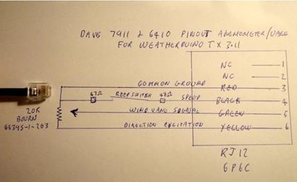
I found someone had reversed engineered the schematic so that was handy. The Anemometer speed cups pulse a reed switch to indicate wind speed. Notes on the web page indicate early versions did not include series resistors so I added one at the surge protector. The wind vane drives a continuous rotation 20k ohm Bourns 6639S-1-203 potentiometer to indicate wind direction.
The Weather Monitor II uses a 2.5V reference voltage across the wind direction pot. I assume this was done to isolate the analog output from digital noise. The WebControl 8 has a 10-bit (1024 count) A/D (analog to digital) converter with 10V maximum input. Using a 2.5V reference voltage would result in very low A/D counts. I opted to power the potentiometer from the WebControl 5V supply and feed the wiper output to the first Web Control analog input. Given the high resistance of the pot the higher voltage is a non-issue. The voltage regulator in the PLC is very accurate but if not it is easy to adjust the firmware switch points to compensate for other voltage as long as it is stable.
The WebControl digital inputs have a 10K pulldown for reliable 0 logic level of unconnected inputs. I reversed the excitation polarity at the pot compared to the Davis implementation. 5V is connected to the junction of the wind speed switch and pot and the other end of the pot is ground. Now the reed switch switches 5V, so it can drive the WebControl digital input directly. This makes the wind direction output voltage maximum when the vane is pointed north, reducing as it rotates clockwise: NE, E, SE, S, SW, W, and NW and finally to 0V at north again. Using a continuous rotation pot is not extremely accurate since there has to be a dead band as the wiper moves from max voltage to min terminal so it does not short out the supply. The Weather Monitor II LCD displays wind direction as 8 compass cardinal points: N, NE, E, SE, S, SW, W, and NW. There is no way to display nonnumeric information on the WebControl so wind direction is displayed as 8 cardinal points in degrees: 0, 45, 90, 135, 180, 225, 270, and 315.
WebControl direction display is updated every 5 seconds.
The table below shows the firmware decision points to drive the display with a 5V supply.
|
Heading |
Resistance |
AD Count |
Display Degrees |
|
N |
0 |
512 |
|
|
N+ |
1,250 |
>480 |
0 |
|
NE |
2,500 |
448 |
|
|
NE+ |
3,570 |
>416 |
45 |
|
E |
5,000 |
384 |
|
|
E+ |
6,250 |
>352 |
90 |
|
SE |
7,500 |
320 |
|
|
SE+ |
8,750 |
>288 |
135 |
|
S |
10,000 |
256 |
|
|
S+ |
11,250 |
>224 |
180 |
|
SW |
12,500 |
192 |
|
|
SW+ |
13,750 |
>160 |
225 |
|
W |
15,000 |
128 |
|
|
W+ |
16,250 |
>96 |
270 |
|
NW |
17,500 |
64 |
|
|
NW+ |
18,750 |
>32 |
315 |
|
N+ |
|
≤32 |
0 |
|
N |
20,000 |
0 |
|
To determine wind speed calibration I used a signal generator to feed different frequencies into the Weather Monitor II and recorded the MPH display. The anemometer speed pulses are feed to the WebControl counter using digital input 1. The Weather Monitor II has a 2 second update cycle. I assume it is measuring pulse interval since low wind speed results in single digit frequency. Accurate pulse timing over the range of expected wind speed is not possible for the WebControl so I chose a 15 second integration period. To convert count to MPH multiplied 15 second count by 2 then divided by 13. The long integration time results in lower reported speed for bursty wind.
The table below indicates the wind speed counter to miles per hour conversion.
|
Freq |
Davis Speed |
WebCntrl Count |
WebCntrl Speed |
|
1 Hz |
3 mph |
25 |
2 mph |
|
2 Hz |
4 mph |
29 |
4 mph |
|
3 Hz |
7 mph |
44 |
7 mph |
|
4 Hz |
9 mph |
62 |
9 mph |
|
5 Hz |
11 mph |
78 |
11 mph |
|
6 Hz |
13 mph |
89 |
13 mph |
|
7 Hz |
16 mph |
106 |
16 mph |
|
8 Hz |
18 mph |
120 |
18 mph |
|
9 Hz |
20 mph |
135 |
20 mph |
|
10 Hz |
23 mph |
149 |
23 mph |
|
20 Hz |
47 mph |
301 |
48 mph |
|
30 Hz |
69 mph |
454 |
70 mph |
|
40 Hz |
92 mph |
608 |
93 mph |
|
50 Hz |
115 mph |
764 |
116 mph |
Data logging
Besides displaying instantaneous temperature, humidity, wind direction and wind speed the maximum wind speed and min/max current day and previous day temperatures are displayed. 8 VAR registers are visible on the web interface.
|
VAR 1 |
System health status |
|
VAR 2 |
Wind direction, 8 cardinal points in degrees |
|
VAR 3 |
Current wind speed in MPH |
|
VAR 4 |
Peak wind speed in MPH |
|
VAR 5 |
Minimum temperature degrees F |
|
VAR 6 |
Maximum temperature degrees F |
|
VAR 7 |
Min temp yesterday degrees F |
|
VAR 8 |
Max temp yesterday degrees F |
At 6:00 AM local time (system ignores daylight savings) an email report is sent and daily min/max values are reset ready for the next reporting period.
Note: the values reported in the email are those when it is actually sent. This can be multiple seconds after the decision is made to send the email so they will be different if they have changed after the firmware decides to send the email.
WebControl 8 Email
The WebControl 8 is able to send email however it does not have enough processing power to use SSL/TLS encryption. This requires an email service that does not require SSL to log in to send email (hard to find these days) or use the more expensive and powerful WebControl32. Another security recommendation is to use a unique email account to accept WebControl outgoing email.
Field Wiring
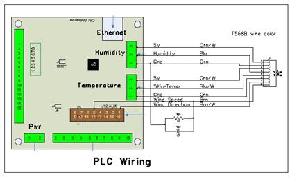
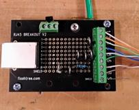
An 8-conductor cable connects the WebControl 8 to the DIY surge protector via an 8P8C modular plug (AKA RJ45). Webcontrol digital inputs have a built in 10k pulldown. I added another 10k pulldown and a .1uf capacitor to reduce noise susceptibility and swamp out any switch contact bounce.
The surge protector in turn connects the outdoor sensors via an 8-conductor cable for the temperature and humidity sensors and a 4-conductor cable to the anemometer. The surge protector is an RJ45 breakout board I found on eBay. I installed 6 6.5V TVS diodes and a heavy ground wire. I also added a 100 ohm series resistor on the wind speed signal as used in later anemometer production. A 1-Wire temperature sensor is installed on the protector to report indoor temperature.
|
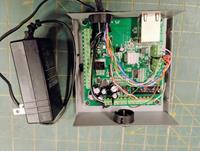
Figure 4 PLC Enclosure |
Figure 5 PLC Data Cable |
|
Figure 6 Surge Protection |
Figure 7 Surge Protector Wiring |
Solar Radiation Shield
 For accuracy the temperature and humidity sensors must
be protected from direct sunlight and surfaces that radiate. I used the Davis
7714 passive radiation shield from our old weather station. It is located on
the north side of a deck post about 12 feet from the west side of the house. The
purpose of the radiation shield is to allow free flow of ambient air while
shielding the sensors from extraneous heat sources. For highest accuracy use
an aspirated radiation shield that provides forced air movement through the
enclosure.
For accuracy the temperature and humidity sensors must
be protected from direct sunlight and surfaces that radiate. I used the Davis
7714 passive radiation shield from our old weather station. It is located on
the north side of a deck post about 12 feet from the west side of the house. The
purpose of the radiation shield is to allow free flow of ambient air while
shielding the sensors from extraneous heat sources. For highest accuracy use
an aspirated radiation shield that provides forced air movement through the
enclosure.
I attached a 6-postion screw terminal strip to the top of the radiation shield to mount the temperature and humidity sensors. The shield houses both the WebControl 8 temperature and humidity sensors along with the ThermPro TP-60 wireless transmitter. Having two independent systems helps to isolated problems.
It is interesting to see how effective the radiation shield is. We have another outdoor temperature sensor used by our greenhouse. It is mounted on the north facing wall of the house about 50 feet from the radiation shield. It is affected by the thermal mass of the house. During rapid temperature swings the two sensors can differ by multiple degrees.
Web Interface
The WebControl 8 includes a web server making data available to any web browser on the LAN. The WebControl 8 web interface is not very beautiful. One of the items on my TO-DO list is to write web server code to integrate all my DIY widgets to make them easier to read and control.
System Status
This page reports input values and calculated results in the VAR registers.
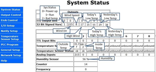
Figure 9 System Status UI
This page enables PLC code execution and enablese digital input 1 to feed the counter. The TTL output configuration is not used and left at default.

Figure 10 I/O Setup UI
Network Setup
I use static IP settings for each of the WebControl devices on our LAN. This insures they do not move around on the network. IP values can also be set using DHCP MAC reservation on most routers. This accomplishes much the same goal however the configuration is lost if the router is replaced.
The RTC is set using NTP (network time protocol) and reverts to hard coded time at power up as it is not battery backed up. If the default all zero IP address is set the pool.ntp.org address is used. I run a local NTP server so point WebControl to it. This has the advantage of providing a single NTP server on the LAN but more importantly after a power outage it is able to service NTP requests prior to internet connectivity being restored.
General Setup
If web polling is enabled web pages are constantly refreshed. 1-wire timing tweaks access timing. For a small short network the default timing should work fine.
Temperature Setup
The 1-wire protocol was originally developed by Dallas Semiconductor who were acquired by Maxim who in turn are now owned by Analog Devices. Each 1-wire device has a unique serial number. This page sets the mapping between device and display. It is also used to select Celsius or Fahrenheit temperature display.
If you purchased your 18B20 temperature sensors on line there is a good chance they are counterfeit so test them against a known temperature standard. I had to throw out the most recent batch I purchased on eBay.
Notify Setup
This page configures email account log and the outgoing email addresses and settings of each message. The system sends two emails. One is at power up and if it detects a temperature sensor failure. The other is sent at 6:00 AM reporting the previous 24 hours highs and lows and the current temperature, humidity, wind speed and direction.
Cost Rollup
The whole idea of this project was to be able to use stuff I had laying around. However if you decide to purchase new/used parts for this project the table below shows the estimated cost as of February 2025.
There is nothing special about the enclosure. I’ve used old set top box enclosures for other projects that need a small chassis.
|
Item |
Cost |
|
Used Davis Weather Monitor II |
$80.00 |
|
CAI Networks WebControl 8 PLC |
$37.50 |
|
AcuRite Radiation Shield |
$13.00 |
|
RJ45 breakout board |
$18.00 |
|
Small enclosure |
$5.00 |
|
LCE6.5A TVS diodes |
$9.00 |
|
6-postion Jones terminal strip |
$2.00 |
|
Analog Devices 18B20 Temperature sensors |
$2.00 |
|
Honeywell HIH 4000 Humidity sensor |
$15.00 |
|
9V 1A wall wart |
$5.00 |
|
Cat 5 cable |
A/R |
|
Total |
~$190 |
*************** PCB Hardware/Firmware version ****************
Hardware: 2.3.8
Firmware: 3.03.32
Customer loop executed every ~50ms (minimal test code)
VAR and RAM initialized to 0 by system at power up
To reset PLC to power up state - update network settings (Send)
RAM location reset to 0 on code upload, VAR not affected
WebControl takes about 400ms to init I/O at power up
Per CAI Support Temp sensors take up to 2 sec to stabilize at power up
Email takes about 1.5 sec to send, no timeout if SMTP server does not respond
TTL inputs have 10k pulldown
Output buffers 10mA per output, 30mA total
A/D 10V full scale 10-bits
Note EMAILQ added FW ver 3.3.19
9V power consumption:
WebControl board: 155ma (Live Ethernet serving web page)
***************** I/O Defs **********************
Analog Inputs
-------------
AIP1 - Wind Direction
AIP2 - not used
AIP3 - not used
Digital Inputs
--------------
IP1 - Wind speed Counter input enabled
IP2 - not used
IP3 - not used
IP4 - not used
IP5 - not used
IP6 - not used
IP7 - not used
IP8 - not used
Digital Outputs
---------------
OP1 - not used
OP2 - not used
OP3 - not used
OP4 - not used
OP5 - not used
OP6 - not used
OP7 - not used
OP8 - not used
Temperature Sensors
-------------------
T1 - Outside Temperature
T2 - Inside Temperature
T3 - not used
T4 - not used
T5 - not used
T6 - not used
T7 - not used
T8 - not used
Temp Sensor status (1 = OK)
------------------
TS1
TS2
TS3
TS4
TS5
TS6
TS7
TS8
Humidity Sensor
---------------
H1 - Outside relative humidity
Email message Identifiers
-------------------------
EM1 - System status (init and temp hard failure)
EM2 - not used
EM3 - not used
EM4 - not used
EM5 - not used
EM6 - not used
EM7 - Morning daily status email (6AM)
EM8 - not used
Variables
--------
VAR1 - System Status: 0 power up, 1 normal, 2 bad temp sensor
VAR2 - wind direction 8-quadrants N,NE,E,SE,S,SW,W,NW in degrees
VAR3 - current wind speed MPH
VAR4 - max wind speed
VAR5 - current day low temperature
VAR6 - current day high temperature
VAR7 - previous day low temperature
VAR8 - previous day high temperature
RAM
---
RAM1 - T1 Temp /10
RAM2 - Bad temp Sensor state: 0=send email, 1-99 debounce counter,
100 OK status, 101 email sent
RAM3 - Scratch - wind direction degrees, wind speed MPH calc
RAM4 - Wind direction next update: 0,5,10,15,20,25,30,35,40,45,50,55 seconds
RAM5 - Wind speed next update: 1,16,31,46 seconds
RAM6 -
RAM7 -
RAM8 -
Web constants
------------
UROM1 - not used
UROM2 - not used
UROM3 - not used
UROM4 - not used
**************************************************
PUINIT
Runs once at power up. Delay for temp sensors to stabilize and sets VAR1
status flag =1
OUTTEMP
Fetches current temperature and sets current day min/max. Debounces bad temp
status and sends email if hard failure.
WSPEED Wind speed 5V sw input Digital 1 to Counter
Runs every 15 seconds at 1,16,31,46 seconds
Counter multiply by 2 then divide by 13 = MPH display speed VAR3
Update max speed each time VAR4 if VAR3 > VAR4
WDIR Wind direction Analog 1 from continuous turn 20k potentiometer
Excitation 5V from Vcc
Runs every 5 seconds
Display 8 quadents in degrees on VAR2
Display 0,45,90,135,180,225,270,315,0
NEWDAY
Sends email at 6:00:03AM (std time) with current temp/humidity/
wind dir and wind speed. Day high wind and min/max temperature
value current day and previous day. After email sent sets
yesterday to current day values and max wind speed to current.
Brute force 5 minute delay after email triggered to insure
mail has been sent before update new day values. EMAILQ did
not work as it appears even if the queue reports as empty the
email has not actually been sent.
If bad temp sensor sets both to 0. Waits 6 minutes to
insure mail has been processed before doing next day update.
RMTTEMP Uses HTTP WEBSET to set VAR8 on Window ventilator:
to current outside temp (T1) once per minute. Suppressed if temp status bad.
WindowVent /api/setvar.cgi?varid=8&value= (no password)
******************* Code *************************
START
TSTEQ VAR1 0
CALLSUB PUINIT
CALLSUB OUTTEMP
CALLSUB WSPEED
CALLSUB WDIR
TSTEQ CH 6
CALLSUB NEWDAY
TSTEQ CS 2
CALLSUB RMTTEMP
END
PUINIT:
SET VAR1 1
SET RAM2 100
DELAY 5000
CALLSUB TEMPSTAT
TSTNE RAM2 100
GOTO PUINIT1
SET RAM1 T1
DIV RAM1 10 RAM1
SET VAR5 RAM1
SET VAR6 RAM1
PUINIT1:
EMAIL EM1
WINIT0:
TSTNE CS 1
GOTO WINIT0
SET RAM5 1
SET COUNTER 0
RET
OUTTEMP:
CALLSUB TEMPSTAT
TSTNE RAM2 100
RET
SET RAM1 T1
DIV RAM1 10 RAM1
TSTLT RAM1 VAR5
SET VAR5 RAM1
TSTGT RAM1 VAR6
SET VAR6 RAM1
RET
WSPEED:
TSTNE CS RAM5
RET
SET RAM3 COUNTER
SET COUNTER 0
MUL RAM3 2 RAM3
DIV RAM3 13 VAR3
TSTGT VAR3 VAR4
SET VAR4 VAR3
ADD RAM5 15 RAM5
TSTGT RAM5 60
SET RAM5 1
RET
WDIR:
TSTNE CS RAM4
RET
SET RAM3 0
TSTGT AIP1 480
GOTO DIRDONE
SET RAM3 45
TSTGT AIP1 416
GOTO DIRDONE
SET RAM3 90
TSTGT AIP1 352
GOTO DIRDONE
SET RAM3 135
TSTGT AIP1 288
GOTO DIRDONE
SET RAM3 180
TSTGT AIP1 224
GOTO DIRDONE
SET RAM3 225
TSTGT AIP1 160
GOTO DIRDONE
SET RAM3 270
TSTGT AIP1 96
GOTO DIRDONE
SET RAM3 315
TSTGT AIP1 32
GOTO DIRDONE
SET RAM3 0
DIRDONE:
SET VAR2 RAM3
ADD RAM4 5 RAM4
TSTGT RAM4 59
SET RAM4 0
RET
NEWDAY:
TSTNE CM 0
RET
TSTNE CS 3
RET
EMAIL EM7
NEWDAY1:
TSTLE CM 5
GOTO NEWDAY1
SET VAR7 VAR5
SET VAR8 VAR6
SET VAR4 VAR3
SET VAR5 0
SET VAR6 0
TSTEQ VAR1 2
GOTO NEWDAY2
SET RAM1 T1
DIV RAM1 10 RAM1
SET VAR5 RAM1
SET VAR6 RAM1
NEWDAY2:
TSTNE CS 1
GOTO NEWDAY2
SET RAM5 1
SET COUNTER 0
RET
TEMPSTAT:
TSTNE TS1 1
GOTO BADTEMP
TSTNE TS2 1
GOTO BADTEMP
SET RAM2 100
SET VAR1 1
RET
BADTEMP:
TSTEQ RAM2 101
RET
DEC RAM2
TSTNE RAM2 0
RET
SET VAR1 2
SET RAM2 101
EMAIL EM1
DELAY 50000
RET
RMTTEMP:
TSTNE RAM2 100
RET
WEBSET URL1 T1
REMWAIT:
TSTEQ CS 2
GOTO REMWAIT
RET
******************* End **************************
Closing thoughts
This was a fun project. It is nice being able to view real time local weather and see the highs and lows of the current and previous day.