|
Schmidt Consulting |
|
Toddler Activity Box |
|
|
|
|
|
Tom Schmidt |
|
12/7/2016 |
|
As a newly minted grandparent I wanted to build a toddler activity box. The box has electronic gizmos on top, plumbing and gears on the sides and a couple of compartments at the front. The device is battery powered so it does not have to be connected to the mains. |
Table of Contents
Overview
As a newly minted grandparent I wanted to build an activity box for our granddaughter. I Realize I’m jumping the gun a little, but it will be there whenever she is ready to play with it. There are lots of pictures of activity boards on the Internet but I felt a board would be cumbersome and create a tip over risk. To address those problems I built a small box, 18 inches wide and 12 inches deep and 12 inches tall. Four casters allow the box to be easily rolled around.
The top is an aluminum panel that mounts most of the electronics. The left side has plumbing parts and a small bulb air pump. The right hand side has motorized plastic gears that can be rearranged. There are two doors on the front, one has a sliding shelf to access a game controller and the other is empty.
The electronics are powered by 6 D batteries accessible via a rear door.

Figure 1 Activity Box
The Box
The box is built with wood I had laying around. The top is an Aluminum sheet that mounts the electronics. I added a couple of stretchers at the top of the box to support the Aluminum panel and notched them to feed the phone and gear motor cables. There are two 6x6 inch doors in the front. Behind each is a small compartment attached to the front of the box. The left has a sliding shelf with a non-functioning game controller. I routed a ¼” channel down the center of the base and used a screw to prevent the controller from coming all the way out. The door on the right has a magnetic switch that turns on a white LED module located at the top of the cavity. At the far right I attached a UK Police Call Box (aka Tardis) key chain retractor. I epoxied a magnet to the bottom of the key chain. When the magnet is brought near the compartment door switch it turns the light off.
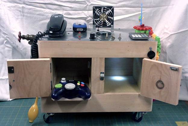
Figure 2 Front Doors Open
Electronics
Always need some electronics on my projects, this one was no different. I wanted to equip the box with stuff that actually does something not just a bunch of passive static devices. Power is derived from 6 D batteries wired in a center tapped arrangement. This lets me power stuff at 4.5 and 9 volts. Except for the fan and gear motor the devices are controlled by a timer. This automatically shuts the system down to conserve battery life. The fan is operated by a pushbutton and the gear motor makes a fair amount of noise so decided not to run it through the power switching circuity to simplify the design.
Electronic Devices:
Ø Telephone
Ø LED flashlight
Ø Fan
Ø Multicolor RGB LED
Ø Analog voltmeter
Ø Motor driven gears
Ø Solar Calculator
Found a working Trimline phone (GE 29195GE1) at our local dump still-good shed. It has a nice LCD display that displays dialed number and a timer. The other features, like telephone number memory require a built in battery that I did not install. The phone is powered from 9 volts.
The flashlight has two modes low and high, which illuminate different LED arrays. I got it from Harbor Freight as a freebie with other purchases. I disassembled a second one and used the LED module for access compartment light and the magnet was attached to the bottom of the Tardis. The flashlight is normally powered from 3 AAA batteries. Removed the back and replaced the battery clips with a couple of wires back to the timer module. Discarded the back and used the same screws and mounting holes to attach it to the panel.
The fan is a 12 volt brushless unit salvaged from some long ago dead electronic device. It runs fine at 9 volts. For safety I attached fan guards on both the intake and exhaust. Unlike the other powered devices the fan is wired directly to the battery via a pushbutton. The fan draws a fair amount of current so wiring it directly reduces the amount of current the timer needs to switch.
I mounted a tricolored RGB LED with each color controlled by a separate switch.
The volt meter has a 10 volt range, connected to a 10-turn pot. The meter was one of the few electronic devices I actually had to purchase.
The gear motor normally operates from a single AAA battery. I used a buck converter to reduce the 9 volts down to 1.5.
The calculator is solar powered so does not require a power connection. I used a bit a double sided foam tape to attach it to the top panel.
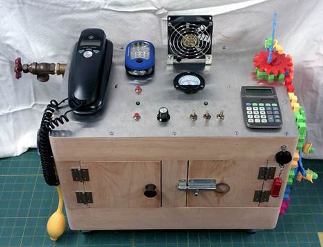
Figure 3 Electronics
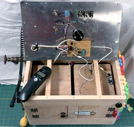
Figure 4 Underside Electronic Control Panel
Timer Module
To extend battery life I used a CMOS 555 timer to control power. Each time the start button is pressed the timer provides about 10 minutes of play time. The battery consists of 6 D cells split into two groups of 3. This yields +4.5 and -4.5 volts referenced to the center tap. A 2N3906 PNP transistor controls the switched +4.5 volt rail and an IRF530A power MOSFET the -4.5 volt rail. The negative rail has higher peak current consumption so I needed a beefier transistor. Where possible I added a series resistor to each load to reduce power consumption. The flashlight and compartment light have a jumper that selects either switched or constant power.
The timer controls everything except the fan (push button) and the gear motor (noisy enough not to be left on by accident.
To protect against polarity reversal connected a diode bridge across the battery and protected each power feed with a 1 Amp fuse.
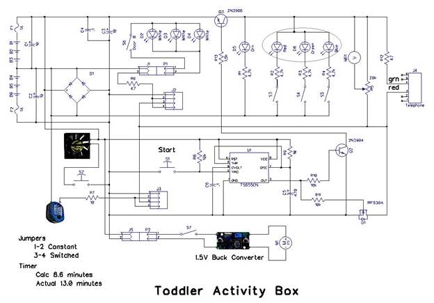
Figure 5 Control Electronics
Battery
The 6 D cells are mounted in two 3 cell battery holders attached to a hinged door at the rear of the box. This allowed me to create a center tapped power supply. Each leg is fused for protection. The fuse holders serve double duty to disconnect wiring if the top needs to be completely removed.
Current Consumption
Standby current drain is 150uA across the 9 volt battery used to power the timer.
The fan is the most power hungry device consuming 170 mA. The gear motor draws about 100 mA from the 9 volt supply running all the gears. Telephone draw is 35 mA and the flashlight is 35/95 mA depending on mode.
Maximum switched current on the +4.5 rail is 45 mA and the -4.5 rail is 170 mA.

Figure 6 Battery Door
Plumbing

Figure 7 Plumbing
I wanted the plumbing section to actually do something. I found a hand football/volleyball bulb inflator on eBay. It is connected it to a 15 PSI pressure gauge, ball valve and hose bib. The hand pump works but it does not have a built in check valve so pressure falls each time the bulb is released. Had not considered that when I bought the pump. When inflating balls the rubber inflation orifice acts as the check valve pressing against the inflation needle to prevent air from escaping.
Most of the fittings are ½” copper. Use a reducer to convert it to the ¼” NTP threads used for air hoses. A tee connects the pressure gauge and bulb. The bulb inflator was a problem. Originally I thought the fittings were 1/8” but that turned out not to be the case.
 Purchased an
inflator kit from a nearby Harbor Freight, which yielded most of the smaller
threaded parts I needed. It came with a reducer from ¼” and a blow tube that
fit the bulb pump threads. Unfortunately the tube was only threaded on one end.
I drilled out the reducer and epoxied the tube to connect the inflator. Not
elegant but it works fine and is strong enough.
Purchased an
inflator kit from a nearby Harbor Freight, which yielded most of the smaller
threaded parts I needed. It came with a reducer from ¼” and a blow tube that
fit the bulb pump threads. Unfortunately the tube was only threaded on one end.
I drilled out the reducer and epoxied the tube to connect the inflator. Not
elegant but it works fine and is strong enough.
The plumbing side was the most expensive part of the box since I had to purchase most of the parts.
Gears
I struggled to figure out what to put on the remaining side. I thought about a random collection of knobs and handles but that did not seem very exciting or engaging. Luckily I found a plastic gear kit on eBay. Screwed them to the side and used the compartment to store the extra parts. Had one extra baseplate so arraigned it so it can be used on top. Too bad the kit did not come with 3 more base plates as there is more room on top. Maybe I’ll bite the bullet and spend another $7.50 to purchase another kit.
One of the modules is a motorized gear powered by single AAA cell, shown in the lower left of the picture. Rewired the module and used a buck converter powered directly from the battery. Connected the buck converter directly to the battery as current draw is fairly high especially at startup or if the motor is stalled. Adjusted the output voltage to 1.5 Volts to keep the motor happy.
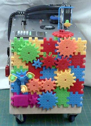
Figure 9 Motorized Gears
Response
Our granddaughter is still way too young to use the activity box. Once she gets a little older I’m anxious to see if it engages her curiosity. When I was little my maternal grandparents had a box of plumbing fittings. I spend many an hour playing with those. Only time will tell.