Design and Installation of Outdoor TV Antenna
Schmidt Consulting
Tom Schmidt
tom@tschmidt.com
Revised 11/30/2017
Originated 11/12/2008
Summary
Digital television (DTV) transition June 12, 2009 motivated me to review our outdoor TV antenna and undertake an upgrade program during the fall of 2008. We live in a fringe area able to receive both Boston and NH stations. Boston stations are 42 miles away; nearest NH station only 13. This paper documents the steps we took to evaluate our options, install a new outdoor antenna and our experience over the years.
In the 2019-2020 timeframe over-the air (OTA) broadcasting will undergo another significant transition. The FCC station repack plan changes the over-the-air landscape by once again reducing the number of TV channels and requiring many stations move to a different frequency or shut down. On the technology front the transition from ATSC 1.0 to ATSC 3.0 digital broadcast standard will allow broadcasters to offer higher resolution programs and integrate broadcast TV with the internet.
OTA TV had fallen out of favor with the rising popularity of cable and satellite providers but is experiencing somewhat of a renaissance. About 20% of American households currently rely exclusively on over-the-air TV and a significant number of cable and satellite subscribers use OTA for one or more TVs. There is much talk of cutting the cord, folks that have canceled cable and satellite TV.
DTV dramatically improves video and audio quality while allowing multiple programs to fit into the same RF bandwidth previously occupied by a single analog program. Many stations now offer one or more standard definition (SDTV) channels as well as a main program in high definition (HDTV). Quality is often better than cable or satellite because channels are not recompressed (transcoded) to fit available capacity. With ATSC 3.0 broadcasters will be able to offer 4k UHD.
Background
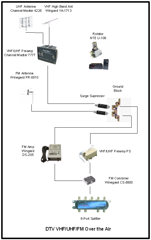
We live in southern NH. This gives us access to both NH and Boston stations. Being 42 miles from Boston in hilly forested New England requires a high gain outdoor rooftop antenna. Our existing outdoor antenna was over 20 years old so the digital transition motivated me to see if anything could be done to improve reception. The old system consisted of separate VHF and UHF antennas mounted on west gable with a mast-mounted preamp. A rotor positions the antenna between NH and Boston stations. A separate omnidirectional antenna was used for FM. TV and FM signals were carried over separate coax cables to outlets throughout the house.
Design goal:
- Receive more stations
- Minimize or eliminate need for rotor
- Integrate FM distribution so all TV outlets have FM capability
- Improve antenna grounding
First off there is no such thing as a digital TV antenna, that is marketing hype. An antenna does not care if it is receiving an analog or digital program. Its purpose is to capture an electric field and deliver it to the receiver. That being said DTV reception is more demanding then analog. Analog slowly degrades as noise increases showing up as snow. DTV is subject to cliff effect. Reception remains perfect until signal falls below a critical threshold. When that occurs the receiver is no longer able to recover the signal. Longley-Rice propagation modeling is used to predict TV coverage area. During the transition planning phase FCC and stations worked together to engineer desired coverage. Modeling criteria has been criticized for producing overly optimistic results. Real world DTV coverage tends to be worse than predicted due to cliff effect in rural areas and multipath interference in urban locations. Whereas with analog the viewer decides how much snow/ghosting to tolerate before deeming a program unwatchable with DTV it is the receiver that makes the determination, reception is either perfect or nothing.
Digital TV, like analog, is affected by multipath. Ideally the signal traveled over a single path from transmitter to receiver. In the real world TV signals bounce off buildings, airplanes, mountains etcetera. Reflected signals are delayed relative to main signal. With analog NTSC TV multipath results in ghosting. Digital ATSC 1.0 tuners used to be very susceptible to multipath. Newer designs do a better job rejecting multipath but if extreme will still corrupt signal.
Fringe TV reception consists of two main components: an outdoor antenna to capture weak signal and a preamp to boost signal to compensate for distribution losses between antenna and TV. The system must have enough gain to receive weak distant signals while not being overloaded by nearby transmitters.
In order to receive the extremely weak fringe signals the antenna needs high gain, but the down side is beam width becomes very narrow requiring accurate pointing. Rural viewers often have stations at wildly divergent compass headings. To deliver an acceptable signal antenna must be precisely aligned to each station. The most common way to achieve this is by using a rotator. The rotor is able to position the antenna to any desired compass heading. The downside is only subsets of desired stations are available at any given antenna position. This is a serious problem for homes with multiple TVs or DVRs.
Cost and convenience must be factored in. Antenna height is normally dictated by structure used to mount antenna. It is possible to erect a tower to provide greater elevation but that is usually not feasible due to cost and aesthetic considerations.
Antenna grounding is critical for safety. A properly grounded antenna bleeds off static charge caused by wind passing over the antenna. It also goes a long way to reducing damage caused by nearby lightning strikes.
Interested readers are strongly encouraged to visit Ken Nist’s HDTV primer site, particularly the antenna section. Much of the information in this paper was derived from Ken’s site.
Over the air TV broadcast
In the US the FCC standardized on the NTSC format in 1941 but widespread commercial broadcast did not occur until after WWII. NTSC is analog as were subsequent color and stereo audio enhancements. Digital transmission offers many advantages and 2009 saw the conversion from analog to digital transmission.
We are currently in another transition period as the result auctioning off more TV channels and the deployment of the next generation digital standard ATSC 3.0.
Broadcast TV uses two frequency bands. Channels 2-13 are Very high frequency (VHF) and 14-51 are Ultra high frequency (UHF). VHF TV channels are further split into two blocks, channels 2-6 (VHF low) and 7-13 (VHF High). VHF low is not ideal for DTV due to man-made noise and propagation characteristics. In most markets there are no digital VHF low stations.
TV channel allocation
In the aftermath of the digital TV transition UHF Channels 52-69 are no longer designated for TV broadcast in the United States. They have been auctioned off for other purposes. This is not the first time broadcast TV lost channels. Channel 1 went away back in the 1940’s and channels 70-83 were lost in the 1980’s. Channel 37 is reserved for radio astronomy. In some urban areas channels 14-20 are used for two-way radio rather than TV. Over the next few years the number of TV channels will be reduced once again as a result of the FCC incentive auction. Going forward there are now a maximum of 35 (2-36) TV channels a drastic reduction from the original 82 VHF/UHF channels.
|
Channel |
Band |
Notes |
|
1 |
VHF-lo |
1948 reassigned public safety land mobile |
|
2-6 |
VHF-lo |
TV – poor choice for DTV |
|
7-13 |
VHF-hi |
TV |
|
14-20 |
UHF |
TV – not available in some urban areas |
|
21-36 |
UHF |
TV |
|
37 |
UHF |
Reserved for radio astronomy |
|
38-50 |
UHF |
2017 reassigned cellular |
|
51 |
UHF |
2011 removed due to cellular interference |
|
52-69 |
UHF |
2009 DTV transition, reassigned cellular |
|
70-83 |
UHF |
1983 reassigned land mobile |
Digital TV (DTV) vs high definition television (HDTV)
Digital TV (DTV) refers to the way program is transmitted. The Advanced Television System Committee (ATSC) standard replaced the older National Television System Committee (NTSC) analog system. Digital TV and high definition TV (HDTV) are often confused. Just because a program is digital does not mean it is high definition. DTV is capable of broadcasting HDTV or a combination of HDTV and standard definition TV (SDTV). Digital transmission is spectrally and temporally more efficient than analog making it possible to deliver not only higher quality but multiple programs, called sub channels. A TV channel that in the past was limited to a single analog program is now able to deliver multiple programs. Each station choses which combination of HD and SD programs to broadcast. ATSC 3.0 ups the ante enabling transmission of 4K Ultra HD.
Virtual channel numbers
A source of confusion is the notion of virtual channels. Virtual channel numbers do not correspond to the actual frequency used for transmission. For example in Boston analog WGBH used to be on channel 2. As with many TV stations much marketing effort went into associating channel 2 with the station call sign. Digital TV decouples the virtual from physical channel. In the case of WGBH it continues to use channel 2 for marketing purposes even though it now broadcasts on channel 19 and various cable systems carry it on entirely different channels.
When determining antenna requirements it is important to understand the difference between physical and virtual channel numbers. TV antennas only care about the frequency used for transmission, the physical channel.
In some instances virtual channel numbers cause problems if you are able to receive multiple stations and they have chosen to use the same virtual channel number. This is not a common problem even in fringe areas as the FCC tries to keep stations wildly separate. But if you are able to receive distant stations may encounter the problem. How the TV reacts to this situation varies by manufacture.
Sub channels
ATSC 1.0 digital transmission, being more spectrally efficient then analog, allows multiple programs to be transported over a single 6 MHz channel. Digital TVs display the main channel number then a dot and one or more sub channels. The number of sub channels is limited by the 19.39 Mbps ATSC 1.0 data rate. As more sub channels are added video and audio quality suffers. Stations use sophisticated multiplexers to merge multiple programs into a single digital stream for transmission.
Finding stations
First step on the path to over the air TV is to determine signal strength of nearby stations. A popular modeling site is AntennaWeb run by the Consumer Electronics Association (CEA). Antenna Web is extremely conservative so it excludes weak stations receivable with a good outdoor antenna. In our case Antenna Web only shows 2 stations when in fact we reliably receive many more. FCC has its own signal strength modeling site. It is much more detailed then Antenna Web and models weaker stations. We mainly use Andy Lee’s TV Fool to model signal strength. Note: as of November 2017 there have been multiple posts that TV Fool does not accurately report effects of FCC repack plan. Both TV Fool and FCC sites provide a detailed signal strength report. TV Fool has two options to analyze signal strength. Location may be specified by street address or exact map coordinates. Using street address is convenient but precise location results in a more accurate estimate in hilly terrain or rural areas.
Fringe viewers typically have access to multiple stations serving different markets. Because stations are far away they require a high gain directional antenna. The down side of directional antennas is pointing accuracy. If the antenna is not accurately aligned signal level is adversely affected. If desired stations are at significantly different compass headings a rotator allows the antenna to be rotated to pick up dispersed stations. Rotors are the bane of multi TV households and digital video recorders (DVR) since at any given time only a subset of stations are viewable.
In designing an antenna system need to carefully consider which stations are of interest to minimize need to constantly reposition antenna. Instead of using a rotor multiple antennas can be aimed at specific stations. In that case antenna feeds must be combined so as to not degrade performance of individual antennas. To optimally combine multiple antennas band pass and band reject filters are used so only the desired frequencies from each antenna are combined. If filters are not used not only are the desired signals combined but so is noise and multipath. This may not be a problem in strong signal areas but can be devastating in fringe. In some cases filtering is easy. For example VHF/UHF combiners are cheap and readily available as are VHF Lo/Hi. Only slightly more expensive are FM/TV combiners. Where design becomes complex and expensive is if stations are at different compass headings requiring multiple antennas each supplying only a few channels within a band.
Chart on the next page shows TV Fool modeling for local stations and predicted receive signal level circa late 2009 shortly after the digital transition. Stations of interest highlighted in yellow.
Channel Assignments (Late 2009) |
||||||
|
RF Chan |
Virt Chan |
Callsign |
Network |
Power dBm |
Dist Miles |
Az True |
|
2-6 |
VHF Low – No local stations |
|||||
|
88-174 MHz |
Broadcast FM (88-108 MHz) 108-174 2-way radio services |
|||||
|
7 |
|
|
|
|
|
|
|
8 |
8 |
WMTW |
ABC (ME) |
-94.5 |
85.1 |
33 |
|
9 |
9 |
WMUR |
ABC (NH) |
-36.1 |
12.5 |
19 |
|
10 |
|
|
|
|
|
|
|
11 |
11 |
WENH |
PBS (NH) |
-63.5 |
34.4 |
43 |
|
12 |
|
|
|
|
|
|
|
13 |
13 |
WYCN |
Ind LP (NH) – Analog |
-86.5 |
11.1 |
108 |
|
Ý VHF UHF ß |
||||||
|
14 |
|
|
|
|
|
|
|
15 |
|
|
|
|
|
|
|
16 |
|
|
|
|
|
|
|
17 |
|
|
|
|
|
|
|
18 |
62 |
WMFP |
RTV (MA) |
-84.5 |
41.7 |
147 |
|
19 |
2 |
WGBH |
PBS (MA) |
-82.9 |
41.2 |
148 |
|
20 |
5 |
WCVB |
ABC (MA) |
-83.0 |
41.2 |
148 |
|
21 |
|
|
|
|
|
|
|
22 |
|
|
|
|
|
|
|
23 |
|
|
|
|
|
|
|
24 |
41 |
WVTA |
PBS (VT) |
-102.9 |
58.6 |
318 |
|
25 |
31 |
WNNE |
NBC (VT) |
-107.4 |
58.6 |
318 |
|
26 |
|
|
|
|
|
|
|
27 |
66 |
WUTF |
Tel (MA) (Spanish) |
-76.1 |
31.1 |
163 |
|
28 |
28 |
W28CM |
WYCN translator analog |
-85.1 |
12.4 |
120 |
|
29 |
27 |
WUNI |
Uni (MA) (Spanish) |
-84.9 |
33.1 |
184 |
|
30 |
4 |
WBZ |
CBS (MA) |
-83.5 |
41.2 |
148 |
|
31 |
25 |
WFXT |
FOX (MA) |
-99.2 |
42.1 |
147 |
|
32 |
68 |
WBPX |
ION (MA) |
-99.1 |
41.7 |
147 |
|
33 |
21 |
WPXG |
ION (NH) |
-64.6 |
31.3 |
35 |
|
34 |
60 |
WNEU |
TEL (NH) (Spanish) |
-40.1 |
12.6 |
19 |
|
35 |
50 |
WZMY |
MyN (NH) |
-81.3 |
15.1 |
111 |
|
36 |
|
|
|
|
|
|
|
37 |
Reserved for Radio Astronomy |
|||||
|
38 |
13 |
WGME |
CBS (ME) |
-106.5 |
97.5 |
38 |
|
39 |
38 |
WSBK |
Ind (MA) |
-93.7 |
41.2 |
148 |
|
40 |
|
|
|
|
|
|
|
41 |
56 |
WLVI |
CW (MA) |
-90.6 |
42.1 |
147 |
|
42 |
7 |
WHDH |
NBC (MA) |
-88.8 |
41.7 |
147 |
|
43 |
44 |
WGBX |
PBS (MA) |
-88.8 |
41.2 |
148 |
|
44 |
6 |
WCSH |
NBC (ME) |
-100.7 |
87.2 |
34 |
|
45 |
|
|
|
|
|
|
|
46 |
|
|
|
|
|
|
|
47 |
48 |
WYDN |
Daystar (MA) Religious |
-99.8 |
41.7 |
147 |
|
48 |
|
|
|
|
|
|
|
49 |
|
|
|
|
|
|
|
50 |
|
|
|
|
|
|
|
51 |
|
|
|
|
|
|
Boston UHF stations are within a degree of one another. WZMY (now WBIN) is an outlier being a UHF station in NH. NH VHF stations are not precisely on the same heading but being nearby are much stronger so modest misalignment is not a problem. The weakest VHF signal of interest is -64 dBm and -99 for UHF. System must be engineered to reliably pick up signals that weak while not being overloaded by strong nearby TV or FM stations.
For readers without an engineering background dB (decibel) is a common method used to specify power level. It is logarithmic rather than linear. Given the huge differences in power it keeps numbers manageable and easy to add/subtract. Decibels are ratios between two quantities. For example a signal 3 dB larger is twice the power, 3 dB smaller half power, 10 dB ten times, 20 dB one hundred times and so on. When used to express power levels it is often referenced to 1 milliwatt, 0 dBm. Strongest signal we are interested in is about – 35 dBm the weakest –95. 60 dB difference means there is a factor of one million between strongest and weakest signal TV receiver has to be able to process.
Selecting equipment
UHF antenna
There is general agreement Channel Master 4228 8-bay antenna is the best all-around UHF fringe antenna. As mentioned on HDTVprimer even though billed as UHF only it can be used on VHF high. Around the DTV transition Channel Master released a new version, the 4228HD, which is lighter and specified for VHF high (channels 7-13) in addition to UHF. Unfortunately it appears to be somewhat less sensitive on UHF then old version. Luckily we are using the old design.
Other candidates for UHF deep fringe are Antennas Direct 91XG and the Fracarro BLU920F. The gain curve for Yagi Corner Reflector antennas peak at the high end. This effect is not nearly as pronounced in 4-bay and 8-bay antennas. A redesigned version optimized for the reduced number of UHF channels would yield modest improvement but so far manufactures have not shown much interest in retooling TV antennas.
Antennas increase gain by becoming more directional. A useful analogy is a searchlight compared to a light bulb. The searchlight focuses light into a narrow beam. High gain antennas need to be accurately aimed to work properly. Directional antennas reject signal received off axis reducing problems with multipath. This is useful in our area due to mountains and rough terrain. Large high gain antennas are vulnerable to wind and ice damage. More is not necessarily better when it comes to selecting an antenna. It does not make sense to use a larger antenna then necessary. The smallest antenna that receives the channels of interest with adequate margin is the best choice.
VHF antenna
There are no VHF low stations in our area. We chose a Winegard YA-1713 VHF high antenna. For the same gain a VHF high antenna is smaller and lighter than an antenna designed to receive the entire VHF band.
With separate VHF and UHF antennas I offset the VHF antenna –105 degrees relative to UHF. When UHF antenna is pointing toward Boston VHF is aligned with WENH, the weaker of the two NH VHF stations. This minimizes need to reposition the antenna.
VHF/UHF preamp
The other key component for fringe viewers is a mast mounted pre-amp. Once antenna has captured weak signal do not want it degraded traveling over coax on its way to TV. Preamp function is often misunderstood. The preamp compensates for distribution losses between antenna and TV it cannot create a signal not captured by the antenna.
The other important benefit of a preamp in weak signal area is improved noise figure. Signal captured by antenna is tiny. It must be amplified before receiver is able to process it. In real world nothing is perfect. In addition to boosting desired signal amplifiers add noise, the greater the noise the more signal that must be captured to overcome it. TV designers are not overly concerned with noise figure (NF). Most viewers receive TV programs via cable or satellite presenting a strong signal. The rest are in fringe areas relying on an OTA antenna and mast-mounted preamp or urban areas with strong signals. When a preamp is used its noise figure dominates not the NF of the TV. Noise figure isn’t normally even listed on TV specifications. In testing DTV receivers FCC found typical UHF NF to be around 7 dB. A good mast mounted preamp will have a much lower NF. In order to ignore receiver noise figure preamp must have enough gain to overcome distribution losses and receiver noise figure.
We selected a Channel Master 7777 preamp with a UHF NF of 2 dB and VHF of 2.8. That means UHF signal can be about 5 dB weaker than if TV was directly connected to antenna. That is a lot of bang for the buck. A nice feature of the CM 7777 is separate inputs for VHF and UHF. This simplifies using separate VHF and UHF antennas.
Rotator
TV stations are at multiple compass headings requiring a rotator. Rotors are the bane of multi TV and DVR households. Pointing the antenna toward one station reduces signal level of the others. We are lucky NH stations are on VHF and Boston stations on UHF. By offsetting VHF antenna by -105 degrees when UHF antenna is aimed at Boston VHF receives both NH VHF stations drastically reducing the need for rotor.
Low cost TV rotators do not track antenna position directly. They use two synchronous motors, one in the control head and another to rotate the antenna. Being synchronous both motors move through the same number of degrees, assuming no slippage. This works well enough but errors build up over time necessitating occasional resynchronization of control head and antenna.
Higher end TV rotators dispense with motorized control head. Instead a microcontroller tracks antenna heading, controls rotor motor and processes IR remote control commands. The microcontroller counts power line transitions to maintain synchronization with rotor. It is much easier to jog rotor a few degrees with microcontroller based unit then electromechanical unit. Our desire was to minimize how often rotor is used. Wanted to control rotor from control head and NOT be forced to use IR remote control. We choose NTE U-106 rotor. Controller has several alphabetic keys used to preset antenna position and clockwise and counter clockwise buttons for fine-tuning. Azimuth display is only two digits. The least significant digit is not displayed. Getting antenna perfectly aligned with true north is difficult so lack of least significant digit is not a major issue.
To fine tune antenna position we monitor TV signal strength indicator and use manual buttons to jog antenna clockwise or counterclockwise.
A nice feature of the controller is it remembers antenna position when turned off. This eliminates need to resynchronize controller after power failure or when turning controller on.
FM antenna
FM broadcast is located between TV channel 6 and 7. FM reception is less demanding then TV but in rural areas reception benefits from using an outdoor antenna rather than the dipole typically supplied with the radio. This can be accomplished by using the TV VHF antenna or a dedicated FM only antenna.
TV Fool has a sister site FM Fool to calculate FM signal levels. This is handy to determine if nearby FM stations are strong enough to cause TV interference. In general signal overload is not a problem unless FM transmitter is closer than 10 miles. Luckily FM signal overload is not a problem for us.
Most FM stations we are interested in come in adequately using automobile whip antenna or properly positioned twin-lead dipole. But some are marginal resulting is high level of background hiss. FM stations, as with TV, are in various locations. I was concerned using the directional VHF High TV antenna, pointed toward NH, would not yield adequate reception of Boston FM stations.
We choose a Channel Master HD-6010 omnidirectional FM antenna. Basically it is just two dipoles stacked on top of one another offset by 90 degrees. Gain for this antenna is 3 dB less then using a single dipole since energy picked up by one dipole is radiated out the other. The advantage is onmidirectional coverage so antenna picks up stations equally well in all directions. This is not precisely correct but works well enough. Luckily FM reception is not nearly as demanding as TV.
FM amplifier
Needed an FM amplifier to boost signal in order to feed multiple locations. I purchased a discontinued Winegard DS-205 16 dB VHF TV amp and removed the FM filter allowing it to be used for FM. FM being lower frequency, is not attenuated as much as UHF allowing amplifier to be located in the wiring closet rather than on the mast.
Combining TV and FM
When combining signals from multiple antennas need to take care to not degrade noise margin. I could have used a regular two-port splitter to combine FM and TV signals. Multiport splitters are not frequency sensitive; they will cheerfully combine or split all signals, including noise and multipath. Winegard has a clever device called a FM combiner (CS-8800) to addresses this problem. Combiner has two inputs one for TV and one for FM. TV input filter attenuates range of frequencies used by FM, 88-108 MHZ. FM input has a band pass filter that only passes FM frequencies. Using this device allows TV and FM to coexist on the same coax while not degrading either. An additional advantage is the CS-8000 introduces less loss then using a splitter to combine TV and FM.
Splitter
Residence has 7 TV/FM outlets. This requires an 8-port splitter that introduces 11 dB of loss. If FM and TV are desired at a given location a 2-way splitter cuts the signal in half resulting in an additional 3 dB distribution loss. A better solution is a TV/FM splitter that has less loss.
UHF & VHF signal budget
TV Fool and FCC sites provide a rough estimate of real world performance. Modeling takes into account terrain but not obstructions like nearby buildings and trees or multipath effects on receiver. Goal is to capture enough power to present a recoverable signal to the receiver even under adverse propagation conditions.
UHF Signal Budget |
|
|
Thermal noise floor 6 MHz TV channel |
-106.2 dBm |
|
Minimum ATSC SNR |
15.2 dB |
|
Antenna preamp noise figure |
2.0 dB |
|
|
------------- |
|
Absolute minimum Rx signal level |
-89.0 dBm |
|
Antenna Gain (Chan 31) |
16.0 dBi |
|
|
------------- |
|
Absolute minimum antenna signal level |
-105.0 dBm |
|
Propagation impairment fudge factor |
10.0 dB |
|
|
------------ |
|
Minimum signal strength at antenna |
-95.0 dBm |
|
|
|
VHF Signal Budget |
|
|
Thermal noise floor 6 MHz TV channel |
-106.2 dBm |
|
Minimum ATSC SNR |
15.2 dB |
|
Antenna preamp noise figure |
2.8 dB |
|
|
------------- |
|
Absolute minimum Rx signal level |
-88.2 dBm |
|
Antenna Gain (Chan 11) |
11.0 dBi |
|
|
------------- |
|
Absolute minimum antenna signal level |
-99.2 dBm |
|
Propagation impairment fudge factor |
10.0 dB |
|
|
------------ |
|
Minimum signal strength at antenna |
-89.2 dBm |
http://www.hdtvprimer.com/ISSUES/erecting_antenna.html
Thermal noise floor for 6 MHz TV channel is –106.2 dBm. ATSC specification requires a minimum 15.2 dB signal to noise ratio. Receiver must be able to decode signal if it is at least 15.2 dB stronger than background noise. Mast mounted preamp has 2 dB UHF and 2.8 dB VHF nose figure. Noise added by the amplifier increases the amount of signal antenna must capture to meet receiver minimum sensitivity. UHF antenna has 16 dBi (isotropic) gain on worst-case UHF channel of interest, VHF antenna has lower gain 11 dBi. Isotropic gain is gain compared to a theoretical antenna that receives equally well in all directions. Combining these factors yield a minimum acceptable signal level at antenna of –105.0 dBm for UHF and -99.2 for VHF.
DTV transmission suffers from cliff effect. As long as signal is even slightly above minimum threshold image/sound is perfect. If signal drops even a little receiver is unable to process it, causing program to pixelate or freeze. To minimum signal level we added a 10 dB atmospherics impairments fudge factor. This compensates for signal fade due to changing atmospheric conditions. Factoring in atmospherics yields desired field strength of at least –95 dBm UHF and -89.2 VHF at antenna.
On paper antenna design is not adequate to receive several weak UHF channels. Weakest UHF channel of interest is -99 dBm and VHF -64. In addition even with roof-mount the antenna is significantly lower than nearby trees. Trees do not have much effect on VHF but almost totally block UHF. Need to accept we will not be able to receive weaker stations 24/7/365. Some will exhibit high occurrence of dropouts making them unwatchable. The good news is in winter when trees lose their leaves reception will improve.
Distribution loss budget
Having expended this effort capturing weak signals we want to make sure they are not attenuated before arriving at the TV. For this we need to examine losses between antenna or preamp and TV. Distribution system gain should be such that signal arrives at receiver 10-20 dB stronger than at antenna. TV receiver NF is about 7 dB want to insure weakest signal at antenna arrives at TV well above TV’s internal NF. On the other hand need to be careful amplifier does not have too much gain. Excessive gain will cause strong stations to overload TV front end.
It is important to keep in mind an amplifier is only able to increase signals captured by the antenna. The role of the amplifier is to compensate for cabling and other distribution loss once the antenna has captured the signal. Signal loss increases with frequency. A given length of coax has greater loss at UHF then VHF. RG-6 coax is the preferred cable for TV distribution systems.
In our system the first coax sections connect the preamp and FM antenna to mast mounted grounding block surge protector. Second section runs from antenna to attic wiring closet. FM/TV combiner injects separately captured FM signal so it can be distributed over the same coax used for TV. Residence has 7 TV/FM outlets necessitating an 8-way splitter. Lastly need to account for coax loss from splitter output to TV. Cable from individual TV outlets to TV itself is typically RG-59 rather than RG-6. It has higher loss the RG-6 but being only a few feet long is not a significant contributor to loss budget.
If FM radio is used at same location as TV need to factor in 2-way splitter or FM/TV splitter. TV/FM splitter can be used to separate TV and FM at the TV with lower loss (.4 dB vs 3.5) then using a splitter. If TV, FM and DVR are connected need to use a 3 or 4-way splitter. This results in loss of about 7 dB as compared to about 3.5 dB for a 2-way splitter.
Signal Distribution Loss Budget |
|||
|
|
FM |
VHF |
UHF |
|
FM/VHF/UHF amplifier gain |
16.0 dB |
23.0 dB |
26.0 dB |
|
Antenna mast coax 10’ |
N/A |
-0.3 dB |
-0.6 dB |
|
Surge Suppressor |
-0.2 dB |
-0.2 dB |
-0.2 dB |
|
Roof ridge coax 30’ |
-0.6 dB |
-0.9 dB |
-1.8 dB |
|
FM/TV combiner |
-0.4 dB |
-0.4 dB |
-0.4 dB |
|
8-way splitter |
-11.0 dB |
-11.0 dB |
-11.0 dB |
|
TV drop coax max 30’ |
-0.6 dB |
-0.9 dB |
-1.8 dB |
|
|
---------- |
---------- |
---------- |
|
Signal at Rx relative to antenna |
3.2 dB |
9.3 dB |
9.6 dB |
Gain is a double edge sword. One does not want an amplifier with too much gain. Doing so may result in overload from strong nearby stations. As long as gain exceeds distribution loss plus receiver NF there is no benefit of additional gain.
Installation

Outdoor antenna
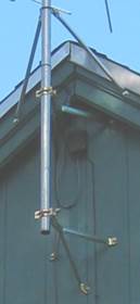
In general higher the better for antennas, toyed with mounting VHF above UHF antenna to reduce wind loading. In the end opted to mount UHF antenna on top to maximize signal capture. VHF antenna is mounted three feet below and offset by –105 degrees. Rotor is two feet below VHF antenna. I used a thrust bearing to reduce rotor loading and increase stability. Bottom of rotor is two feet above roof peak. FM antenna is centered between roof peak and bottom of rotor. This provides three feet of separation between antennas. The greater the separation the less they interact with one another.
A weather station wind speed and wind direction sensor is located below the rotor.
Overall length of the mast is about 14 feet. Being gable mounted it is not practical to guy antenna. To reduce possibility ice or wind will take it down used heavy gauge 1.5” diameter mast rather then more common 1.25.” Most mast sections are 5-foot. It is possible to order 10-foot heavy duty 16-guage mast. Instead opted to use 1-1/4 EMT (electrical metallic tubing) commonly known as conduit. 1-1/4” trade size conduit has an OD of 1.510” with .065” wall thickness resulting in very strong mast. Each mast section ended up being about 8-feet long.
 In December
2008 soon after we installed the antenna Southern NH experienced a severe ice
storm. Many trees were knocked down and we were without power for a week. In
December 2009 strong wind stripped shingles off the roof. Halloween 2011 we
experienced another severe ice storm and lost a number of trees. Antenna came
through with flying colors however in 2009 and 2012 high winds caused the mast
to tip slightly. This was due to the way the gable brackets are constructed.
The triangular portion of the bracket is very strong. But at the triangle apex
it extends about three inches to the mast clamp U-bolt. This portion is
flexible and susceptible to bending in high winds.
In December
2008 soon after we installed the antenna Southern NH experienced a severe ice
storm. Many trees were knocked down and we were without power for a week. In
December 2009 strong wind stripped shingles off the roof. Halloween 2011 we
experienced another severe ice storm and lost a number of trees. Antenna came
through with flying colors however in 2009 and 2012 high winds caused the mast
to tip slightly. This was due to the way the gable brackets are constructed.
The triangular portion of the bracket is very strong. But at the triangle apex
it extends about three inches to the mast clamp U-bolt. This portion is
flexible and susceptible to bending in high winds.
To reduce mast length above gable bracket purchased a U-bolt and located it approximately at roof peak. I used two pieces of ½” EMT to fashion supplemental support brackets. Flattened the ends and bent them so they could be attached to the mast U-bolt and lag bolted to roof structure. This reduced unsupported mast length by about a foot but more importantly provides a hard mount to take the stress off the gable brackets.
Antennas are directional in both azimuth and elevation. Rotor takes care of pointing antenna in correct azimuth. Given marginal signal wanted to do everything possible to maximize capture efficiency. If signal arrives more then a few degrees above or below antenna horizontal centerline signal strength is reduced. This is not a significant factor for FM or VHF but is for UHF.
We live in wooded area. View toward UHF stations is blocked by 70’ high tree line 200’ away. Even though antenna is mounted on roof trees are about 40’ higher then antenna. Trees block almost all UHF signal. To the antenna it looks like signal originates at treetop level. Tilting antenna up 10 degrees points it at skyline maximizing signal pickup.
Since I chose electrical conduit for mast thought it would be easy to contact local electrical contractor and have conduit bent 10 degrees. Turned out no one was interested in doing a one off bend. Contacted a local muffler shop but they did not want to do it, concerned their equipment would crush conduit.
Fell back to plan B. Fabricated a bracket to offset lower antenna mount using four “L” reinforcing brackets. This resulted in a hollow box 3.75” on a side. Bracket hole spacing was close to antenna U-bolt pattern minimizing filing and drilling. Because UHF antenna is no longer parallel to mast was careful not to deform antenna mounting bar. Supplied U-bolts were too short due to large mast and tilt offset, replaced them with ¼” –20 bolts. Bracket tilts antenna up about 8 degrees. Was not able to conduct experiments with antenna mounted vertically and tilted so do not know if tilting antenna is effective at increasing signal.
Channel Master Preamp has two switch selectable options, 1) combined or separate VHF/UHF input and 2) FM trap on/off. Switch access requires removing amp from housing. We use individual VHF and UHF antennas so selected separate inputs and switched FM trap in since we are using a separate FM antenna.
Coax from VHF/UHF preamp needs a loop between upper and lower masts so upper mast is able to rotate. To minimize stress on coax sleeved upper and lower section where it is cable tied to mast with short lengths of small diameter automotive hose. This insures coax experiences a gentle bend radius.
Fabricated antenna and wired it up. Temporally mounted antenna to deck for testing by drilling 1.5” holes in a couple of scrap 2x4s and screwing them into railing.
Removed old antenna and installed new heavy duty wall brackets. Brackets were drilled for ¼” fasteners and came with lag screws for building attachment. Did not think that was adequate. Enlarged holes and used 5/16” toggle bolts.
Complete assembly is pretty heavy and unwieldy. I was not about to walk up ladder with entire antenna stack. Removed VHF antenna, FM antenna, and lower mast section from stack. Upper mast section now consists of just UHF antenna, preamp, rotor, and wiring. Attached lower mast to house bracket set just high enough so when upper section is attached rotor temporally rests on upper wall mount. My son went up on the roof and I climbed ladder with upper section. Connected upper mast to lower, then we used a short section of 2x4 to temporally raise assembly high enough to attach VHF antenna. I was careful to mark correct antenna position during preassembly. Then we used a longer 2x4 to set antenna at correct height. Then we attached the FM antenna and weather station to lower mast. Bolted everything tight and congratulated ourselves for job well done and not falling off roof.
It is important to keep water out of coax connectors. At antennas and grounding block used Coax-Seal to wrap connectors. Stuff is pretty tenacious so install it only after system has been fully tested. Plastic is degraded by Solar UV. We used black, rather than white, cable ties to minimize effects of UV degradation. The TV and FM coax cables routed through the roof peak would be difficult to replace. To protect them from sunlight slipped a piece of black split wiring loam over each.
Installed a small plastic utility box as a junction box mounted under the eaves. Cable for rotor is spliced in J-box, as is wiring for weather station.
Lightning and static protection
TV antenna is likely highest object near your home. As such makes an unintentional lightning rod. Lightning packs a tremendous amount of energy. Lightning protection provides low impedance path to Earth and bonds all metallic conductors together to minimize potential differences during lightning events.
National Electrical Code (NEC) Article 810 requires antenna be bonded to building ground system with minimum 6 AWG copper wire. This minimizes voltage difference between antenna and rest of the house. Years ago when I installed the original antenna common practice was to use 8-gauge solid Aluminum wire to bond antenna mast to building ground system, typically a nearby copper cold water pipe. Antenna is at opposite end of house from electrical service entrance, I installed a supplemental ground electrode for the antenna. Typical ground electrode sold for TV use is only 5 feet long. Longer is better, so purchased a standard service entrance 8-foot ground rod. 6-AWG bare stranded copper wire connects antenna mast to ground rod and bonds antenna to building ground system. PVC conduit and conduit body protect ground cable below exterior siding until it enters the ground.
Two coaxes enter building, one for TV, one for FM. A dual F connector grounding block, mounted on mast wall bracket, grounds both coax shields. Each coax is protected by a gas tube surge suppressor connected to grounding block. Protectors limit voltage between center conductor and shield in event of lightning event. Rotor cable and old aluminum ground wire enter building at the same location. Reconnected old ground wire to mast even though grounding task has been superseded by improved grounding/bonding system.
Good grounding and bonding is not just for lightning protection. Air movement over antenna builds up static charge, just like a Van de Graaff generator. Proper grounding provides a path to drain off charge rather than having it discharge though expensive electronics. Proper grounding also potentially improves reception by minimizing stray current flow through coax shield.
Wiring closet
Antenna and rotor cables run along roof ridge to a second floor wiring closet. TV coax connects to preamp power supply then to TV input of FM/TV combiner. FM coax feeds dedicated FM amplifier then combiner FM input. Combiner output feeds 8-port passive splitter. Individual drop cables feed coax outlets throughout the house. Rotor cable is spliced to two cables. Intent was to allow rotor controller be used at multiple location within the house but have never actually used the second location.
The splitter frame is bonded to the electrical system equipment grounding conductor.
OTA DTV experience
As to be expected with anything as significant as transition from analog to digital TV broadcasting there was a significant amount of post transition tweaking. In our area the most significant change was WHDH’s decision to remain on UHF. Initial plan was to move back to VHF Channel 7. VHF digital coverage turned out to be smaller than expected resulting in numerous viewer complaints.
In the years since the transition many stations have added sub channels or made transmitter and antenna changes to improve reception.
Stations go through multiple steps to build or modify broadcast facilities. They submit an application that is reviewed by FCC. If FCC accepts application station is granted a construction permit. Once construction is complete and verified station license is updated.
“Technical Data and Screencaps” at Rabbit Ears or FCC TV Database Query can be used to check station status. FCC codes licensing information with a prefix indicating type of service and a status indicator. For our purposes the relevant FCC record types are:
DT – Prefix denotes full service digital station
DT-LIC - Full service digital operating license
DT-CP or DT-CP-MOD - Full service digital construction permit or modified permit
DT-APP – Full service digital application
LD – Prefix denotes low power digital
DC – Prefix denotes low power digital Class A
TX – Prefix denotes translator transmitter
TV fool signal strength modeling is based on FCC license and construction permit data. Optionally TV Fool allows modeling based on station application requests. Application requests are proposed changes not yet approved by the FCC. Being able to see predicted signal strength based on application requests provides a heads up on future changes. Caution is advised about using application data as it may be withdrawn or modified by FCC or station.
A modeling quirk to be aware of is once FCC grants a construction permit TV Fool uses that information to predict receive signal strength. Unfortunately there is no easy way to identify when a station completes its upgrade other than to seeing FCC status transition from construction permit (CP) to license (LIC). This means viewing experience may differ from modeled prediction.
If you are having difficulty receiving a station check Rabbit Ears or FCC database, may find reassuring information that station is working to increase coverage area. This process has gotten confusing due to the FCC repack plan since many stations need to move to a different channel. In that case a CP isn’t just a change to antenna or transmitter but a move to an entirely different frequency.
The chart below shows viewing results and current signal strength modeling displaying both noise margin (NM) and receive power level. TV Fool added noise margin to the report so I included both noise margin and power for compatibility with the 2009 chart. Noise margin column assumes typical TV receiver characteristic to compute whether or not a signal is recoverable. NM needs to be at least 0 dB.
TV Fool station ranking (Jan 2017) |
|||||
|
Callsign
|
Network |
RF chan |
Virt chan |
NM dB |
Power dBm |
|
WMUR |
ABC |
9 |
9 |
54.8 |
-36.0 |
|
WNEU1 |
TLM |
34 |
60 |
51.0 |
-39.9 |
|
WPXG1 |
ION |
33 |
21 |
30.2 |
-60.6 |
|
WENH |
PBS |
11 |
11 |
28.3 |
-62.5 |
|
WUTF1 |
FUT |
27 |
66 |
14.0 |
-76.8 |
|
WYCN-LP2 |
Famnet |
36 |
13 |
9.9 |
-80.9 |
|
WBIN2 |
MY |
35 |
50 |
9.5 |
-81.3 |
|
WGBH |
PBS |
19 |
2 |
9.5 |
-81.4 |
|
WCVB |
ABC |
20 |
5 |
9.5 |
-81.4 |
|
WUNI1 |
Uni |
29 |
27 |
9.1 |
-81.8 |
|
WMFP |
Ind |
18 |
62 |
8.2 |
-82.7 |
|
WBZ |
CBS |
30 |
4 |
7.8 |
-83.1 |
|
WBPX |
ION |
32 |
68 |
7.3 |
-83.5 |
|
WGBX |
PBS |
43 |
44 |
3.7 |
-87.2 |
|
WHDH |
NBC |
42 |
7 |
2.7 |
-88.1 |
|
WLVI |
CW |
41 |
56 |
2.4 |
-88.4 |
|
WSBK |
Ind |
39 |
38 |
-1.9 |
-92.8 |
|
WFXT |
Fox |
31 |
25 |
-2.5 |
-93.4 |
|
WMTW1 |
ABC |
8 |
8 |
-4.7 |
-95.6 |
|
WYDN1 |
Daystar |
47 |
48 |
-8.2 |
-99.0 |
Note 1: WNEU, WPXG, WUTF, WUNI, WMTW, WYDN don’t care stations.
Note 2: WYCN, WBIN never received.
Green – good signal
Yellow – occasional no signal
Red – frequent no signal
WGBX was a big disappointment, as we watch a lot of PBS. Real world reception is worse than stations modeled with lower signal strength. I contacted station and was advised they are transmitting at full rated power and using licensed antenna. The good news is WENH and WGBH have joined ranks. WENH is now broadcasting pretty much the same programs as WGBH/WGBX.
WBIN is a no show, even with antenna pointed in the right direction. WBIN (WZMY) had been viewable in analog. Contacted station and was informed they are transmitting at full licensed power. Station uses relatively low power but more important here in hilly NH their antenna is rather low.
We are not able to receive WYCN. Low power stations typically use a fairly low antenna so terrain obstruction is a serious impediment. WBIN and WYCN are at different heading then Boston stations necessitating use of the rotor even if we were able to successfully receive them.
WMTW was a surprise, we receive it randomly, had not considered checking for Maine stations because they are so far away. WMTW is near the heading we use for NH VHF stations. It is the only Maine station we receive, not able to receive any Maine UHF stations. We already receive MA and NH ABC affiliates so there is not a lot of value, mainly just fun being able to receive such a distant station once and a while.
Not able to receive either nearby Vermont stations WVTA and WNNE. Both were extremely snowy in analog and on the wrong side of a mountain.
With WHDH remaining on UHF and WBIN and WYCN a no show rotor is no longer needed. Use is limited to fine-tuning antenna direction. Occasionally even able to receive NH WPXG with antenna pointed toward Boston, WPXG is the NH version of Boston WBPX.
Overall fairly pleased with upgrade, able to consistently receive 8 of 13 local full service stations of interest and 10 most of the time. Counting sub channels we now have access to 30 TV channels, many more then in the days of analog TV.
Evolving OTA environment
When planning a TV antenna system it is prudent to be mindful of future changes and enhancements. The two that affect over-the-air TV are the FCC station repack plan as a result of the 2016/2017 incentive auction and deployment of ATSC 3.0 a new digital TV standard; unfortunately it is not backward compatible with ATSC 1.0.
FCC station repack
The number of channels allocated to TV have been greatly reduced over the years and designated for other purposes. The most recent reduction reassigns channels 38-50. In 2016 the FCC conducted an incentive auction. The winners will use the bandwidth to improve cellular network. Some stations have decided to receive a pay out and shut down. Many that chose to remain will have to move to new channels over the next few years. When planning your TV antenna it is important to understand the local situation. As a minimum it will require rescanning your TV, at worst will need the change your antenna or give up viewing some stations. The RabbitEars site has detailed information about the Repack plan broken down by market. For example here in the Boston designated market area (DMA) that includes southern NH: 7 stations are shutting down, 11 will move and 4 are able to remain on the same channel. Due to the need to coordinate the changes to minimize interference with other stations the conversion is being phased in over a number of years. Repack will be complete by mid-2020.
Table below shows post repack Boston DMA channels:
|
New Chan |
Current Chan |
Callsign |
Phase |
Date |
|
5 |
19 |
WGBH-TV |
4 |
Aug 2019 |
|
9 |
9 |
WMUR-TV |
n/a |
|
|
10 |
10 |
WWDP |
n/a |
|
|
11 |
11 |
WENH-TV |
n/a |
|
|
19 |
29 |
WUNI |
4 |
Aug 2019 |
|
20 |
30 |
WBZ-TV |
4 |
Aug 2019 |
|
21 |
39 |
WSBK-TV |
8 |
Mar 2020 |
|
22 |
32 |
WBPX-TV |
4 |
Aug 2019 |
|
23 |
33 |
WPXG-TV |
4 |
Aug 2019 |
|
27 |
27 |
WUTF-DT |
n/a |
|
|
29 |
34 |
WNEU |
4 |
Aug 2019 |
|
32 |
43 |
WGBX-TV |
8 |
Mar 2020 |
|
33 |
20 |
WCVB-TV |
4 |
Aug 2019 |
|
34 |
31 |
WFXT |
4 |
Aug 2019 |
|
35 |
42 |
WHDH |
8 |
Mar 2020 |
Stations of interest are highlighted in yellow.
In our case we are losing several stations but our current strategy of using a UHF antenna pointed toward Boston and a VHF-hi toward WENH still works. The change of WGBH from UHF to VHF-lo means we will lose reception. VHF –hi antenna is pointed northeast not southeast toward Boston. Several years ago WENH and WGBH merged due to funding problems in NH; by and large they broadcast the same programs so losing access to WGBH is not all that significant.
ATSC 3.0
ATSC 3.0 is the next generation digital TV broadcast standard and will be phased in over the next several years. This is voluntary there is no cutoff date as there was during the 2009 analog to digital conversion. ATSC 3.0 provides significant improvement in the amount of information that can be transmitted over each 6 MHz TV channel and has improved compression using high efficiency video coding (HEVC) H.265 codex that requires less bandwidth for a given picture quality. With ATSC 3.0 broadcasters will be able to offer higher resolution 4K UHD or more subchannels. It is IP centric enabling broadcasters to combine one-to-many broadcast with one-to-one Internet access. It will also enable mobile TV and enhanced emergency alerting.
Antennas and amplifiers don’t care how the signal is encoded. However receivers: TVs and DVRs will need to be upgraded to receive ATSC 3.0. To prevent unduly impacting viewers the FCC requires broadcasters continue using ATSC 1.0 and simulcast existing programs on ATSC 1.0 and 3.0 for at least 5 years. Due to the reduced number of channels allocated to TV this will be more difficult than during the analog to digital transition. It is likely stations will enter into agreements with one another to share transmitters. Mass deployment of ATSC 3.0 is expected in the 2020 timeframe.
Appendix A - Bill of Material (2008 prices)
|
Qty |
Description |
Mfg |
Pt # |
Price |
|
1 |
UHF antenna |
Channel Master |
4228 |
$50 |
|
1 |
VHF high antenna |
Winegard |
YA-1713 |
$40 |
|
1 |
FM antenna |
Winegard |
HD-6010 |
$30 |
|
1 |
VHF/UHF preamp |
Channel Master |
7777 |
$50 |
|
1 |
Rotor |
NTE |
U-106 |
$70 |
|
1 |
Thrust bearing |
NTE |
TB-105 |
$22 |
|
A/R |
Rotor cable |
|
|
|
|
A/R |
RG 6 coax |
|
|
|
|
2 |
1½” 16 gauge mast |
|
1 ¼” EMT |
$31 |
|
1 |
HD wall mount 12” |
Channel Master |
9034 |
$20 |
|
5 |
4” 5/16” toggle bolts |
|
|
$5 |
|
4 |
3-1/2” L brackets |
|
|
$3 |
|
1 |
1½” U bolt |
|
|
$2 |
|
1 |
Aux mast support |
|
½” EMT |
$2 |
|
2 |
3” ½” lag bolts |
|
|
$1 |
|
1 |
Dual ground block |
Holland |
GRB-2DHR |
$1 |
|
2 |
Surge suppressor |
TII |
210 |
$8 |
|
A/R |
#6 stranded bare wire |
|
|
$.44 ft |
|
1 |
8’ ground rod |
|
|
$11 |
|
1 |
Lug (ant mast) |
|
|
$3 |
|
1 |
Clamp (ground rod) |
|
|
$5 |
|
1 |
Clamp (water pipe) |
|
|
$5 |
|
1 |
#6 Split bolt |
|
|
$2 |
|
1 |
½” plastic conduit |
|
½” NMT |
$2 |
|
1 |
½” conduit body |
|
|
$3 |
|
1 |
VHF Amp |
Winegard |
DA 0205 |
$15 |
|
1 |
FM combiner |
Winegard |
CA-8800 |
$16 |
|
1 |
8-Port splitter |
Holland |
GSV-8 |
$8 |
|
A/R |
Black cable ties |
|
|
|
|
1 |
Connector seal |
Coax-Seal |
25-7955P |
$9 |
|
1 pk |
100 RG6 F connectors |
Digicon |
DS6_100 |
$32 |
|
1 pk |
100 Coax clips |
|
SKY32213NW |
$2 |
|
|
|
|
|
------- |
|
|
|
|
Total |
~$500 |
Suppliers
Warren Electronics Distributing Co.
Appendix B - Tooling
Having expended a lot of effort to extract signal out of the air did not want to lose it due to poor coax connector termination. TV distribution uses 75-ohm coaxial cable and F series connectors. Unlike other coaxial connectors F series does not have a center pin. Inner cable conductor connects directly to female receptacle. Connector outer shell provides threaded fitting and extends shield. Key to good high frequency operation is to minimize signal perturbation introduced by connector.
F connectors fall into two broad categories, crimp and compression. Crimp style connectors slide over shield and under outer jacket. A ring is crimped over cable jacket making electrical contact between shield and inner portion of connector. The problem with crimp connectors is crimp has multiple faces while cable is round. This results in unequal contact between connector and shield. Crimpers come in two styles narrow and wide. Typical bargain store crimpers are only about a 1/8 of an inch wide, commercial quality crimper is about ½ inch.
The best F connectors are compression. Compression style connectors have been adopted by the Cable and Satellite TV industry. Compression connectors consist of an inner and outer concentric section. Compression tool pushes both sections together with great force resulting in high quality 360-degree contact with shield.
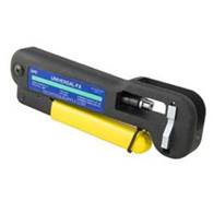
I decided to use compression connectors. Purchased Ripley Universal-FX compression tool ($55) and Cable pro PSA596 coax stripper ($25). Stripper makes precise cuts to remove outer jacket and inner insulation. Another handy tool is Holland CIT F-connector wrench ($5). Wrench is convenient for tightening coax connectors in tight places.
When purchasing a compression tool be sure it is the correct model for the specific brand of connector you are using.
|
|
|
|
|
Ripley Universal-FX Compression Tool |
Cable Pro PSA596 Coax Stripper |
Holland CIT-1 F-Connector Wrench |

|
|
|
Appendix C - Rotor troubleshooting
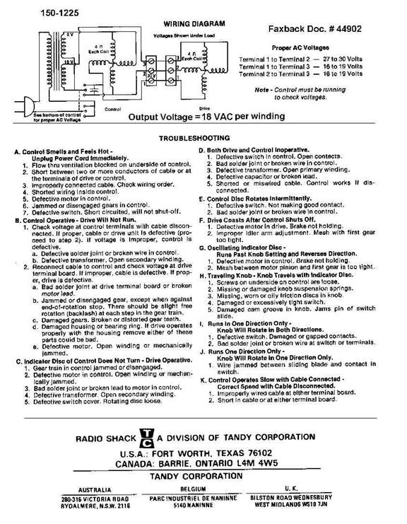
TV rotors are simple devices but the lack of online information makes troubleshooting a challenge. If the rotor stops working measuring voltage at the three terminals is not very useful. Unless of course voltage is zero when control head is attempting to reposition antenna. In that case there is a short in the wiring or more likely the control head has died. Three wires connect to field coils in the rotor to the control box, with power off there should be continuity between all combinations of the three. If not there is an open somewhere either in the cable or rotor motor.
TV rotors do not sense antenna position directly. Ham rotors have a position sensor in the rotor so they always report correct position. If accurate positioning is critical or the antennas are large consider using a Ham rotor. To sense antenna position TV rotors use a synchronous motor to position the antenna and another in the control head. They are turned on simultaneously, so ignoring slippage, remain in synchronization. To resync the rotor move it to the extreme stops. Higher end TV rotors replace the motor in the control head with a microcontroller, but the principle is the same. The controller counts power line transitions to display rotor position.
In order to reverse direction rotors use a two-phase motor typically powered by a 30 volt step down transformer in the control head. Pin 3 is typically common and pins 1 and 2 are the field coils. The control box energizes one winding directly the other through a capacitor. To reverse direction the connections are reversed. Microcontroller based units simply replace the mechanical switch with relays to control direction.
I had linked to a rotor schematic on the Radio Shack site but with bankruptcy the link no longer works so I’ve embedded it into this document.