|
|
|
2nd Generation Wood Heat Controller |
|
|
|
|
|
Tom Schmidt |
|
|
Updated 10/12/2021
Originated 4/6/2013
Tom@tschmidt.com
http://www.tschmidt.com
|
The greenhouse project was so successful that soon afterward I decided to upgrade our 25 year old first generation wood heat controller to bring it into the 21st century. Our primary heat source is a cord wood stove in the basement. The new system uses the same WebControl8 PLC as the greenhouse it: monitors flue temperature, controls fans to distribute heat within the house, brings in outside combustion air and controls a water pump to increase heat capture from the wood stove. In additional it monitors greenhouse state and warns of plumbing leaks. |
Table of Contents
Preheat Tank Temperature Display
Greenhouse Controller Integration
Greenhouse Impending Freeze Signaling
Greenhouse Basement Fan Signaling
Greenhouse Controller Health Status
WebControl8 Programmable Logic Controller
Additional Fire Safety Features
Smoke & Carbon Monoxide Detectors
Front Panel Controls and Indicators
DC Power Distribution and Control
Appendix B – Well Pump Interlock
Appendix C – WebControl8 Configuration Pages
Appendix D – WebControl8 PLC Code
Appendix E – PID Controller Configuration
Overview
Our house is an open floor plan two story Cape. When we designed it many years ago investigated various heating options. We choose a wood stove located in center of walkout basement. Locating stove in basement keeps dirt out of the main living space and allows passive heat transfer to all three floors. Pretty pictures seen in architectural magazines aside, heating with cord wood is messy. Nice being able to limit dirt to the basement and not track in snow. Resistive electric baseboards serve as backup heat source. Electric heat is expensive in our location so we hardly ever use it, but nice having an alternative heat source just in case. We recently installed a minisplit heat pump system to cool the house in summer and augment the wood stove in winter.
A two story open stairway near the stove allows unimpeded vertical airflow. A pair of small fans above the stove blows hot air up and larger second floor fan blows air back into basement. Due to high level of insulation even without fans there is minimal temperature stratification. This is important during power outages so area near stove does not overheat.
Because house is so tight depressurization is a problem, a fan assisted fresh air intake near the stove brings in outside air.
Stove is a Tempwood (no longer in business) top loader rated at 55,000 BTUs. Two manually operated air inlets control burn temperature. They run wide open when fire is started then are closed down to control burn temperature.
At first we used a magnetic thermometer to monitor flue temperature. It was easy to dislodge and did not provide audible over temperature warning. If inlets were not closed down in a timely manner stove ran very hot until someone noticed and went downstairs to damp it down. For the 1st generation controller I obtained several used Type J thermocouple digital temperature panel meters with BCD outputs and designed a simple comparator circuit to sound an alarm when stove was too hot. That was replaced in this system with a temperature controller using the more common Type K thermocouple.
Domestic hot water is provided by an electric water heater. During winter the wood stove acts as a preheater and in summer a solar batch heater in the greenhouse does the same reducing need for expensive electrically heated hot water.
 I installed
a Holly Solar Products heat exchanger
in the stove plumbed to a 30 gallon insulated storage tank. The company still
exists but is no longer in the heat exchanger business. System is a passive thermosiphon loop. Hot
water, being lighter than cold, rises to top of the heat exchanger pulling in
heavier cold water from bottom. As long as stove is hotter than the tank, heat
is transferred from stove to storage tank.
I installed
a Holly Solar Products heat exchanger
in the stove plumbed to a 30 gallon insulated storage tank. The company still
exists but is no longer in the heat exchanger business. System is a passive thermosiphon loop. Hot
water, being lighter than cold, rises to top of the heat exchanger pulling in
heavier cold water from bottom. As long as stove is hotter than the tank, heat
is transferred from stove to storage tank.
The advantage of using a preheat tank rather than adding the thermosiphon loop directly to the water heater is a much lower starting temperate. Well water entering the preheat tank is about 45F vs 130F for the electric water heater allowing stove to transfer significantly more energy. It also means there is no need for a check valve in the thermos phone loop. There is not much force moving the water through the loop so even a swing check valve is a significant impediment.
A PTRV (pressure temperature relief valve ) is plumbed into the tank. It opens if water gets too hot or pressure too high. This is an important safety feature as a boiling water explosion is extremely dangerous. Mythbusters did an experiment to see what happens when a water heater explodes due to excessive pressure. The video is pretty dramatic.
Wood stove preheat tank is plumbed into the electric water heater cold water feed. As hot water is used the electric heater draws replacement water from preheat tank. When stove is operating “cold” water entering electric heater is warmer than normal reducing or eliminating need for additional energy to heat the water. During the summer a solar batch heater in the greenhouse acts as a preheater reducing summer energy use. Implementing a preheat strategy has the advantage of not requiring any modification of the electric water heater while greatly reducing annual electricity consumption.
System works so well that during periods of cold weather and light hot water consumption preheat tank becomes hot enough to open PTRV discharging excess water. Having worked hard cutting/stacking/splitting cordwood this waste is rather heartbreaking. The PLC monitors preheat tank temperature and when it reaches a temperature higher than the electric water heater it switches on a small circulator pump. The pump transfer water from the electric heater to the inlet of the preheat tank, significantly increasing total energy storage and almost completely the need to dump excess hot water.
In addition to monitoring wood stove operation the system provides two auxiliary functions. If the greenhouse controller is unable to maintain adequate temperature or if there is a leak near the water heater or well pressure tank the alarm sounds.
1st Generation Controller
The original system used hardwired logic driven by flue and water temperature thermocouple displays. The BCD temperature outputs were processed to sound an alert if flue temperature was too high and control the preheat tank pump. Fans were controlled by a line voltage thermostat. Normally unit was turned on at the beginning of a burn by the front panel pushbutton. The thermostat served as a backup turning the unit on whenever the fans were on.
2nd Generation Controller
With the successful implementation of the greenhouse controller I decided to see if I could update the old design to add features to increase safety and convenience. Software enables more sophisticated control functions then the old hardwired system. Plus it was another fun project to undertake.
Another consideration driving the redesign effort is the digital panel meters I used are no longer available so if they fail I’m out of luck. Long term replacement is something to consider when designing this type of equipment. The old system was in operation for 25 years. Over that time had to redesign the power supply when the original failed and replace the meters with spares due to a lightning strike. Hopefully the new system will last as long. I purchased spares that can be placed into service if the originals fail. This buys time to design a replacement years down the road. As much as possible I tried to use the same major components as the greenhouse controller to minimize spares cost.
Flue Temperature Monitor
The most important feature is flue temperate display and alarm. When fire is started stove air inlets need to be wide open. Once fire is going inlets are closed down to reduce flue temperature. Too hot a burn stresses chimney and is a potential fire hazard as air around stove and chimney overheat. This wastes energy as air leaving the chimney is still hot. On the flip side running stove too cold causes creosote to form as newly loaded wood begins pyrolysis. This increases air pollution and poses a potential chimney fire hazard as the creosote condenses in the chimney and builds up on the flue liner. This wastes energy as the volatile gas component of the wood is not being burned so does not contribute to heating. Goal is to burn wood hot enough prevent creosote deposits and low enough to capture most of the heat before gas leaves the chimney. Ideal flue temperature at the stove is between 300 – 500F (150 – 250C).
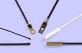
Temperature Probe
Given the high temperature involved thermocouple is the measurement technology of choice. Thermocouples generate a small voltage when the junction of dissimilar metals is heated, called the Seebeck effect. This voltage is very small so special analog processing is needed to display temperature.
|
|
|
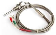

The original controller used Type J thermocouples since that is what the panel meters needed. The new controller uses Type K. Type K is more common and better suited for flue temperature measurement.
Thermocouples have two upper bounds on temperature, that of the conductors themselves and the insulation material. Exceeding maximum conductor temperate can permanently alter calibration. Exceeding insulation rating may result in shorts as the insulation is deformed or destroyed due to excessive temperature. Type K thermocouples are suitable for high wood stove temperature, but only if the insulation is also rated for high temperature. I chose an exhaust gas temperature (EGT) probe rated at full Type K temperature of 1250C. This is significantly hotter than worst case flue temperature.
The other consideration when picking a thermocouple is probe construction. There are three types of thermocouple probes: bare junction, grounded junction, and ungrounded junction. For our purposes ungrounded junction is best. The probe shell completely surrounds the thermocouple junction and insulates it from the probe shell. This eliminates measurement problems due to stray voltages and protects it from combustion byproducts. The stove is grounded by virtue of the copper plumbing used to connect the heat exchanger. This provides a static discharge path protecting thermocouple electronics. The shell slows down response time a little but that is of no concern in our application.
EGT thermocouple probes go for about $25. The probe I purchased is bent in 90 degrees and has a compression fitting designed to screw into a female 1/8” NPT (national pipe thread). The sheet metal flue is too thin to thread directly so I drilled a hole and used a nut to secure it. This is a simple a method to keep the probe from becoming dislodged; it does not have to be gas tight.
PID Temperature Controller
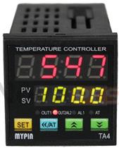 There
are numerous low cost PID
(proportional integral derivative) temperature controllers on the market. I picked
a MYPIN TA4-RNR that goes for about $30 on eBay. The unit displays flue and set
point temperature. Controller interface is via two relay outputs, one is closed
when temperature is too low (heating mode) the other at high temperature alarm.
I chose relay outputs to isolate the controller from the rest of the circuitry.
Having two outputs allowed me to program a high and low temperature threshold
to drive a tri-color LED. Blue indicates too cold, green OK, and red too hot.
An audible alarm is trigged if temperate becomes excessive. PID functionality
is not used; the controller is simply programmed for heating mode with fixed
set-points for low and high temperature threshold.
There
are numerous low cost PID
(proportional integral derivative) temperature controllers on the market. I picked
a MYPIN TA4-RNR that goes for about $30 on eBay. The unit displays flue and set
point temperature. Controller interface is via two relay outputs, one is closed
when temperature is too low (heating mode) the other at high temperature alarm.
I chose relay outputs to isolate the controller from the rest of the circuitry.
Having two outputs allowed me to program a high and low temperature threshold
to drive a tri-color LED. Blue indicates too cold, green OK, and red too hot.
An audible alarm is trigged if temperate becomes excessive. PID functionality
is not used; the controller is simply programmed for heating mode with fixed
set-points for low and high temperature threshold.
Buttons at the bottom set operating parameters that are stored in non-volatile memory.
The PID controller is AC powered. I used a small solid state relay (SSR) to switch it on/off in conjunction with the rest of the system.
Fresh Air Inlet and Duct Fan

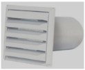 The house is very tight; timber frame construction with
stressed skin wall and roof panels, so depressurization is a problem. An insulated
flexible 4” duct runs from the stove to an inlet on the north side of the house
with a large bore screen to keep out critters. Outside air is ducted to a grill
on the wall above the stove bringing fresh air into the basement. At the stove
grill I added a normal sized screen to prevent small insects from entering the
basement.
The house is very tight; timber frame construction with
stressed skin wall and roof panels, so depressurization is a problem. An insulated
flexible 4” duct runs from the stove to an inlet on the north side of the house
with a large bore screen to keep out critters. Outside air is ducted to a grill
on the wall above the stove bringing fresh air into the basement. At the stove
grill I added a normal sized screen to prevent small insects from entering the
basement.
I used a pair of back-to-back 4” to 6” adapters to mount a 6” AC Tjernlund EF-6 180 CFM duct boost fan near the stove grill. A front panel toggle switch selects whether fan runs continuously or only when stove is in operation.
House Air Circulation
In the event of power failure heat from the stove propagates throughout the building passively. However using fans reduces temperature stratification increasing comfort throughout the house. A pair of small savaged computer fans directly above the stove blow air into the living room and a larger fan located in a second floor closet blows air back to the basement.
The controller uses Dallas (Maxim) 1-wire digital sensors allowing software to control fans. A sensor located at the controller’s front panel monitors temperature near the stove and a second one at the upstairs fan reports 2nd floor temperature. Fans are AC powered controlled by a SSR (solid state relay). A tri color LED indicates air temperature: blue cold (fans off) green OK (fans on) red too hot – audible alarm sounds.
I recently added a front panel toggle switch to select whether fan runs continuously or only when air temperature near the stove is high enough. The intent is to run the fans continuously during the winter when we are not using the stove and relying entirely on the heat pump for basement heating for more uniform basement temperature.
Wood Stove Water Heater
During the winter the wood stove supplies most of our domestic hot water. The stove reduces electricity needed to make hot water by preheating water in a 30 gallon insulated storage tank. Extracting heat from the wood stove is passive using a thermosiphon heat exchanger. I’ve documented our entire solar and wood water heating system here.
Preheat Tank Temperature Display
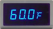 I
wanted to display preheat tank temperate but the PLC does not have provisions
to drive a display. I added a standalone temperature display that uses its own
temperature sensor. The readout is configured to display in Fahrenheit.
I
wanted to display preheat tank temperate but the PLC does not have provisions
to drive a display. I added a standalone temperature display that uses its own
temperature sensor. The readout is configured to display in Fahrenheit.
Originally I used the same 1-wire temperature module as the greenhouse. The sensors are kept powered up constantly but the display and other electronics are only powered when the controller is active. On rare occasions the temperature display did not read the 1-wire sensor correctly. So I replaced the display with a similar one that uses a thermistor to measure temperature.
Preheat Tank Pump
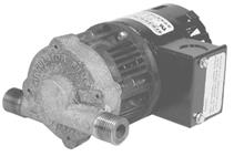 To
increase storage capacity to capture more energy a small circulator pump is
plumbed between the electric water heater hot-water outlet and preheat tank
cold water inlet. The pump is turned on when preheat tank reaches a temperature
somewhat above that of the electric water heater. The pump transfers water
from the electric water heater back to the preheat tank increasing thermal
storage by using both preheat and electric water heater tanks.
To
increase storage capacity to capture more energy a small circulator pump is
plumbed between the electric water heater hot-water outlet and preheat tank
cold water inlet. The pump is turned on when preheat tank reaches a temperature
somewhat above that of the electric water heater. The pump transfers water
from the electric water heater back to the preheat tank increasing thermal
storage by using both preheat and electric water heater tanks.
The transfer of water reduces preheat tank temperate allowing more heat to being captured from the stove. Using the electric water heater increases storage capacity by about 50%. We rarely have a situation anymore where the preheat tank PTRV dumps excess hot water. Part of this is also a lifestyle choice. Knowing we have lots of hot water becomes a good time to do a little extra laundry.
A 1-wire digital sensor measures preheat tank temperature. The preheat tank already has a temperature sensor that reports temperature to the greenhouse controller. PLC controller firmware allows the controllers to share information. However I have not yet implemented that feature. Until that time a separate sensor is used. This results in 3 temperature sensors attached to the preheat tank hot water outlet, 1-wire sensor feeds greenhouse, another 1-wire sensor feeds the woodstove controller and a thermistor sensor feeds the woodstove controller temperature display. A SSR controls pump power and a LED on the front panel illuminates when the pump is running. A check valve prevents cold water from bypassing the electric heater when hot water is being drawn.
Water Heater Emergency Cutoff
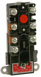 Electric
water heaters have a resettable temperature limit thermostat in addition to the
heating element thermostat. If water temperate exceeds maximum thermostat
setting of 160F it trips cutting off power to the respective heating element.
During periods of extreme cold and low water use water may exceed that
temperature causing thermostat to trip. The event will probably go unnoticed for
a while as the wood stove is making lots of hot water during cold weather.
However once weather warms up water temperature will be too low.
Electric
water heaters have a resettable temperature limit thermostat in addition to the
heating element thermostat. If water temperate exceeds maximum thermostat
setting of 160F it trips cutting off power to the respective heating element.
During periods of extreme cold and low water use water may exceed that
temperature causing thermostat to trip. The event will probably go unnoticed for
a while as the wood stove is making lots of hot water during cold weather.
However once weather warms up water temperature will be too low.
The over temp thermostat has a red reset button. To restore operation need to remove the protective cover and press the reset button. Typical residential water heaters have two elements one at the bottom and a secondary at the top. The one on the top is only energized during periods of high water use when water temperature in the tank gets too low. “Cold” water from the preheat tank enters the electric water heater tank from the bottom via a dip tube, so that ends up being the hottest part of the tank. Some heaters have ECOs on both thermostats some only at the one at the top of the tank.
BTUs Gained – KWHs Saved
Well water entering preheat tank is roughly 45 degrees Fahrenheit (7C) in winter. Raising water temperature to 160F (71 C) takes 28,738 BTUs (160 – 45 x 30 gal x 8.33 BTU).
Electric water heater is 55 gallons set to 120F (49 C). Increasing water temperature to 160F takes 18,326 BTUs (160 – 120 x 55 x 8.33 BTU).
It takes 8.4kwh to raise 30 gallons of water to 160F at a cost of $.17kwh each tank of water heated by the stove saves $1.40. Adding the 55 gallons from the electric water heater saves another 5.4kwh costing $.92. The only significant cost of using the electric water heater to increase storage capacity was $150 for the high temperate pump and a few watts to run it. Actual savings of course depend on stove operating time and water usage. With a family of four, winter hot water energy consumption is about half that of summer prior to adding the greenhouse batch heater. With addition of greenhouse batch collector now have lower hot water cost summer and winter.
Note: in calculating BTUs we are ignoring effect of temperature change on weight.
------------------------------- Caution ------------------------------------------
Water temperature above 120 F dramatically increases risk of being scalded.
Use of tempering valve or antiscald valve decreases risk.
|
Temperature |
Time to produce 3rd degree burns on adult skin |
|
160 F (71 C) |
½ second |
|
150 F (66 C) |
1.5 seconds |
|
140 F (60 C) |
5 seconds |
|
130 F (54 C) |
30 seconds |
|
120 F (49 C) |
>5 minutes |
|
100 F (38 C) |
Safe Temperature |
Greenhouse Controller Integration
The greenhouse controller uses a multi-tiered strategy to maintain adequate winter temperature. If passive temperature moderation is insufficient the greenhouse controller activates a fan to blow warm basement air into the greenhouse. If it is unable to maintain adequate air temperature it sends out a freeze warning email and flashes the front panel freeze warning LED. The good news is that so far this event has never occurred. However, if it does it will probably be in the wee hours of the morning when no one is at a computer to respond. I wanted another method of impending freeze notification. The stove controller has an audible alarm so it was natural to expand its functionality to include the greenhouse freeze event.
Greenhouse Impending Freeze Signaling
The 1-wire temperature sensors used by the greenhouse controller use 5V, Gnd, Data. I used a 4-conductor cable to wire the greenhouse temperature sensors so used the fourth as the freeze alert. During a freeze event greenhouse controller pulls this line low turning on an optoisolator. The output wakes up wood stove controller and provides a digital input to the PLC so it is able determine freeze event is active. When a freeze condition the greenhouse status LED flashes red and activates the audible alarm. If the controller was powered down this even wakes it up.
Greenhouse Basement Fan Signaling
Because the house is very tight blowing air from the basement into the greenhouse risks depressurizing it. To make sure wood stove controller is on when the greenhouse basement fan is running, and hence the wood stove fresh air fan is also on the freeze signal is pulsed active for 200ms when the greenhouse fan is first turned on and again at 0 and 30 minutes past the hour if the fan is still on. This wakes up the controller and firmware ignores the short freeze event. This insures the wood stove controller is awake and the idle timeout has not turned it off while the greenhouse basement fan is running. As long as the wood stove controller is on so is the fresh air duct fan is bringing in makeup air so the house does not become depressurized.
Greenhouse Controller Health Status
I wanted to provide an indication of greenhouse controller health. If greenhouse power is lost (it’s on its own GFCI circuit) it will likely go unnoticed for some time. The temperature sensor cable 5 volts provided a convenient way to monitor status. To maintain metallic isolation between greenhouse and stove controller an optoisolator is used to monitor presence of 5 volts on the greenhouse temperature sensing cable. If 5 volts is lost the controller wakes up, turns the greenhouse status LED flashing red and generates an audible alert.
Plumbing Leak
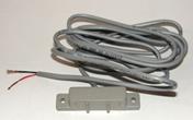 I
recently added plumbing leak detection to the wood stove monitor. Two GRI
2800 leak sensors are used to detect water leaks, one at the electric water
heater and the other at the well pressure tank. These are the two most likely
leak sources. The sensors have two electrodes at the bottom. When water makes
contact with them it switches from a high impedance to low impedance state
activating the alarm. During a leak condition the wood stove controller wakes
up, turns the plumbing leak LED flashing red, activates the audible alarm and
sends an email.
I
recently added plumbing leak detection to the wood stove monitor. Two GRI
2800 leak sensors are used to detect water leaks, one at the electric water
heater and the other at the well pressure tank. These are the two most likely
leak sources. The sensors have two electrodes at the bottom. When water makes
contact with them it switches from a high impedance to low impedance state
activating the alarm. During a leak condition the wood stove controller wakes
up, turns the plumbing leak LED flashing red, activates the audible alarm and
sends an email.
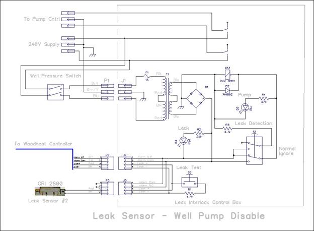
Well Pump Disable
Our water comes from a well. When a leak is detected the controller inhibits the well pump to minimize the amount of water discharged. The N.C. (normally closed) relay contacts in the wood heat controller open, breaking the circuit to the leak interlock control box preventing the well pump from operating. The interlock box consists of the low voltage transformer powered when the well pressure switch activates. As long as the N.C. contacts on the wood stove controller remain closed the high current relay in the interlock box applies power to the well pump. In the event of a leak, the low voltage circuit is broken prevent to pump from operating.
The well pump pressure switch includes a lower pressure lockout. In addition to normal operation turning the well pump on at low pressure and off at high if the pump cannot maintain minimal pressure the switch trips off and needs to be manually reset by lifting the control lever on the side if the switch. This provides another level of protection, if there is a massive leak the well pump is not able to maintain water pressure causing the pressure switch to trip.
A front panel switch disables leak sensing. This is handy if it is a false alarm; say a small condensation puddle near the well pressure tank.
The leak interlock control box, located next to the well pump controller includes a leak test button. This simulates a leak to verify the monitoring circuit is working correctly.
Stove Work Light
 The
old controller had no provision for a work light to illuminate stove and cord
wood storage bin. I’m stating the obvious but stove is hot while in operation.
Walking by it in the dark is dangerous and wood needs to be added to the stove
from time to time. Turning on the main lighting in that part of the basement
seems like overkill just to check the stove and load a few sticks of wood.
The
old controller had no provision for a work light to illuminate stove and cord
wood storage bin. I’m stating the obvious but stove is hot while in operation.
Walking by it in the dark is dangerous and wood needs to be added to the stove
from time to time. Turning on the main lighting in that part of the basement
seems like overkill just to check the stove and load a few sticks of wood.
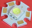
I had never played around with white LEDs before so this seemed like a good excuse. I purchased a Cree XLamp ultra-bright white LED module rated at 350ma with a Vf of 4 volts. LEDs are highly directional which for our application is ideal. The light cone illuminates stove and wood storage bin providing enough light to safely load the stove without having to turn on general purpose basement lighting. At full rated current the LED is much brighter than needed so I used a 47 ohm resistor in series with the 9V supply to limit current to 115 ma. The LED is on whenever the controller is on.
Operating Modes
The controller needs to determine if there is a fire in the stove. At power up the controller sets itself to non-heating mode, VAR1 = 0. If the flue temp bit goes high, indicating flue temperature exceeds 300F, VAR1 is set to 1, indicating heating mode. This information is used to set idle timeout duration, whether to send an end of session email and to enable the house fans.
Audible Alarm
 There
are multiple sources of audible alarm: 1) flue over temp, 2) air over temp, 3)
greenhouse freeze/fail 4) plumbing leak. If any of these conditions occur the
respective LED flashes red and the alarm sounds. The system uses a Mallory Sonalert
to generate an annoying attention getting pulsing sound. The Sonalert is powered
from the 9V supply controlled by an open collector driver.
There
are multiple sources of audible alarm: 1) flue over temp, 2) air over temp, 3)
greenhouse freeze/fail 4) plumbing leak. If any of these conditions occur the
respective LED flashes red and the alarm sounds. The system uses a Mallory Sonalert
to generate an annoying attention getting pulsing sound. The Sonalert is powered
from the 9V supply controlled by an open collector driver.
Alarm Silence
Once the alarm has your attention it is annoying having to listen to it until the condition is resolved. A front panel push button allows the alarms to be temporally silenced. If the situation is not remedied the alarm sounds again a short time later. The silence feature works differently in case of a greenhouse freeze/fail or leak event. Pressing the silence button permanently silences these alarms conditions until they no longer exist or the controller is power cycled. The respective LED continues to flash, even if the alarm is silenced, until the problem is resolved.
Really Loud Alarm
We have another audible warning system that alerts based on inputs from several high temperature sensors monitoring the house and outbuilding. The wood stove controller can be programmed to activate this system if the primary alarm is ignored. If the alarm condition persists for 5 minutes and the silence button has not been pressed the loud alarm is activated making it harder to ignore. To make the alarm distinctive it cycles on/off every few seconds.
 WebControl8 Programmable Logic Controller
One of the nice aspects of the CAI networks WebControl8 is that it includes a built in web server. This allows any PC on the LAN to monitor wood stove status and 1-wire temperature measurements.
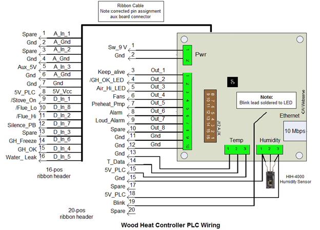
The device provides 8 digital inputs, 3 10-bit analog inputs, 8 digital outputs, 8 Maxim/Dallas 18B20 1-wire temperature sensors, and a humidity sensor using a Honeywell HIH4000. The humidity sensor is not used for control functions but provide a convenient display of basement relative humidity. WebControl8 implements a simple scripting language. User code is generated offline and pasted into the system.
User Settings
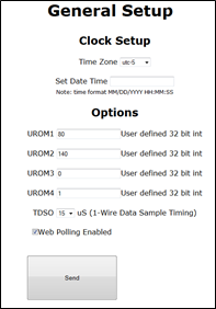 The
controller has 4 web settable values. This is a convenient way to tune system
operation without having to reload PLC code.
The
controller has 4 web settable values. This is a convenient way to tune system
operation without having to reload PLC code.
1. UROM1 house fans on temperature
2. UROM1 circulator pump on temperature
3. UROM3 is not used
4. UROM4 enables/disables loud alarm feature
This page also sets time zone for the RTC.
If web polling is checked the displayed page is continuously refreshed in the web browser.
If 1-wire cable is long the TDSO parameter can be used to adjust sample timing.
Unfortunately title and units of measure are not end-user configurable. To make setting values more user friendly at power up and each time any of the UROMx settings are changed the parameter checker is invoked. An email is sent at power up if any are out of range and each time a value is changed. The email indicates if values are correct and information about the correct range and units.
System Status
The System Status screen displays various values and registers. VAR 1 indicates whether or not the system is in heating mode, 1 indicates stove heating mode. VARS 2 and 3 record the starting temperature in the basement and second floor. Var4 is the shutdown idle timer, it displays minutes past the hour when system will automatically shut down. The other VARS are used for various housekeeping functions.
The Input and Output bits display the various digital controls.
Temperature 1 is temperature near the wood stove. It is used to determine when to turn on fans. Temperature 2 is second floor closet. It is not used by the controller but provide a convenient indication of overall house temperate. Temp 7 is the preheat water tank. It is used to control the pre heat tank pump. Humidity is measured by a sensor located on the PLC. This is a display, the controller does not use this input.
Analog input 3 is the constant 5V supply used to enable automatic wakeup; the other two analog inputs are not used. Refer to the user code section for more details about bit assignments.

Email Alerts
The system generates three types of emails: 1) settings change, 2) end of heating session report and, 3) equipment problems.
|
|
|


End of Session
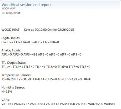
If the controller is in heating mode it sends an end of session email just before shutting down. The email includes beginning basement (VAR2) and upstairs (VAR3) temperature as well as current basement (T1), upstairs (T2) and preheat tank (T7) temperature.
Temperature Sensor Failure, Greenhouse failure, Plumbing leak
Emails are sent on the following error conditions: temperature sensor failure, greenhouse 5V fail and plumbing leak. Only one email sent per event. If the error is corrected and it reoccurs another email is sent.

Additional Fire Safety Features
In addition to the purpose built wood stove controller we have several other fire safety devices.
Smoke & Carbon Monoxide Detectors
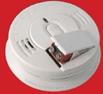 House,
including stove area, is protected by multiple interconnected smoke alarms.
Units are AC powered and battery backed ionization detectors. Battery backup is
important during periods of power failure to maintain fire warning capability.
One of the units is a combo smoke and carbon monoxide detector. These alarms
are completely independent of the stove controller.
House,
including stove area, is protected by multiple interconnected smoke alarms.
Units are AC powered and battery backed ionization detectors. Battery backup is
important during periods of power failure to maintain fire warning capability.
One of the units is a combo smoke and carbon monoxide detector. These alarms
are completely independent of the stove controller.
Heat Sensors

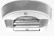 A temperature
detector located on the ceiling above the stove triggers an alarm if air
temperature exceeds 190 degrees F (87.8 C). There are several of these
detectors located throughout the house and outbuilding to act as a backup to
the smoke detectors. Combustion appliances may overheat causing a dangerous over
temperature situation while not emitting smoke to trip the ionization smoke
alarms.
A temperature
detector located on the ceiling above the stove triggers an alarm if air
temperature exceeds 190 degrees F (87.8 C). There are several of these
detectors located throughout the house and outbuilding to act as a backup to
the smoke detectors. Combustion appliances may overheat causing a dangerous over
temperature situation while not emitting smoke to trip the ionization smoke
alarms.
The temperature warning system has its own power supply and horn. System uses two types of sensors: supervised – normally closed and unsupervised – normally open. Commercial systems often implement supervision to detect sensor faults.
These sensors are separate from and set to a much higher temperature than the air over temperature alert implemented by wood stove controller software. If temperature near one of the sensor exceeds 190F the contacts either open or close (depending on sensor type) and the horn activated until temperature is reduced to safe level.
The stove controller’s loud alarm feature is used to sound the alarm by energizing a normally open reed relay to simulate an unsupervised temperature sensor. In order to uniquely identify the source of the alarm the stove controller toggles the warning horn on and off every three seconds to produce a distinctive sound.
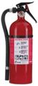 Fire Extinguishers
Multipurpose fire extinguishers are located at strategic locations throughout the house and outbuilding. I tried to choose locations that would not be blocked in the event of fire.
Fire extinguishers are classified by letter code indicating the type of fire they are effective against and a numerical value indicating size, the larger the number the larger the fire. Typical residential extinguishers are rated ABC and come in 5 or 10 pound size.
A – Ordinary combustibles
B – Liquids
C – Safe for use on electrical equipment
D – Combustible metals
Theory of Operation
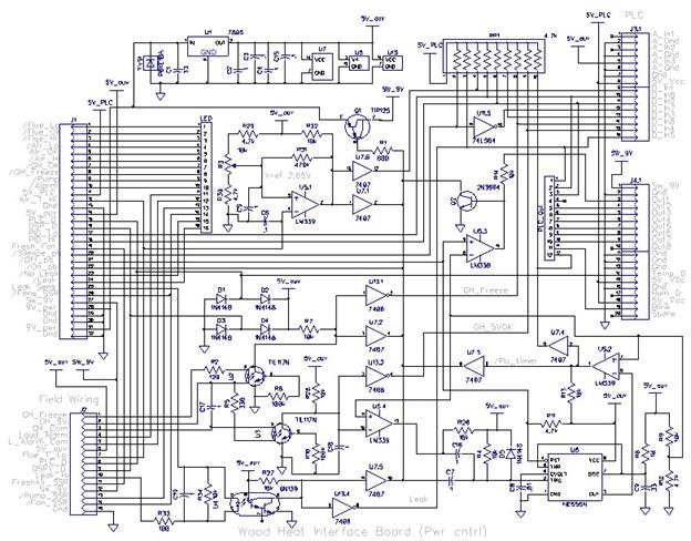
The controller consists of several off the shelf components and a custom kludge interface board.
A Type K thermocouple PID controller is used to monitor flue temperature. It has two relay outputs that close at low and high temperature thresholds. The controller displays flue temperate and control setpoint. The PID function is not used; controller is set for heating mode with simple setpoints for low and over temperature outputs.
A digital panel meter, using a dedicated thermistor temperature probe, reports preheats water tank temperature.
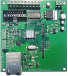
A CAI networks WebControl8 is the heart of the system implementing a programmable logic controller (PLC) and a web based user interface.
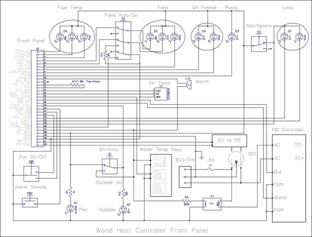
Front Panel Controls and Indicators
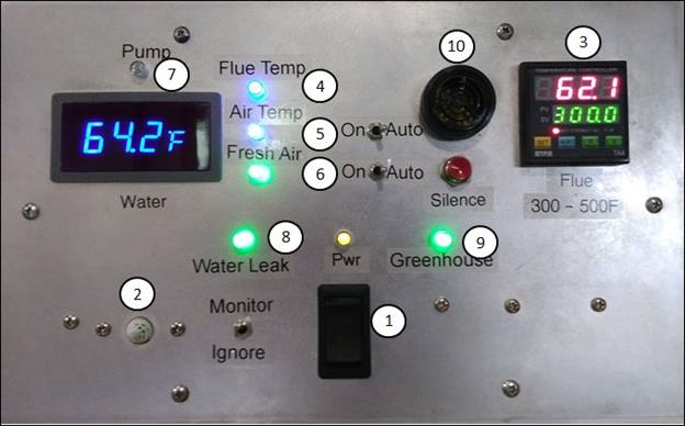
1. Momentary rocker switch – turns unit on or off. Amber power indicator is on in both standby and run mode indicating AC power is available. In some situations the manual shutoff function is inhibited. Controller is also turned on automatically when temperature at stove is higher than the controller.
2. Temperature sensors - a 1-wire temperature sensor is located behind the plastic grill to report basement air temperature. A NTC thermistor is mounted behind the front panel, in thermal contact with it, to provide thermal mass as part of the automatic stove turn on function.
3. Flue temperature PID controller - upper display indicates flue temperature, smaller green display underneath indicates minimum acceptable flue temperature. Status LEDs indicate “heating” mode – flue is below set point and alarm if flue temp exceeds 900F. Buttons are used to set operating parameters stored in non-volatile memory. PID function is not used, just simple “heating” mode and over temp warning via contact closures.
4. Flue temperature LED: blue too cold <300F, green OK, flashing red too hot >900F.
5. Air temp LED: blue fans off, green fans on, flashing red too hot >115F. Switch selects manual or automatic control of circulator fans. Fan turn on temperature set via UROM1
6. Outside air intake LED: green fan on whenever unit is active. Switch selects manual or automatic control of fresh air fan.
7. Preheat water tank temperature display. Green LED above the display is illuminated when temperature exceeds the electric water heater temperature and circulator pump is on. Pump temperature set via UROM2
8. Plumbing leak LED: green all is well, flashing red leak detected. Switch disables leak detection and turns LED off. An active leak disables well pump to minimize the amount of water due to the leak.
9. Greenhouse status LED: green all is well, flashing red temperature is extremely low or failure of greenhouse power.
10. Audible alert - active if any indicators are red. Silence pushbutton used to temporally silence flue and air, and permanently silence plumbing leak and greenhouse fail alert until either error goes away or power cycle. If audible alarm is ignored for long time (5 minutes) a louder alarm is pulsed on off. This is the same alarm used by high temperature fire detectors located at various locations in the house and outbuildings. This alarm is independent of the normal smoke/CO alarms. This feature can be enabled/disabled vial UROM4.
System Power Control
Due to the different ways the controller is activated power control logic is fairly complex. A wired-or scheme is used to allow multiple signals to turn on the controller on, and last-man-out to turn it off.
Stove in Use Detector
I wanted the system to turn itself on automatically when the stove is in use. This insures controller is active during the burn even if it is not turned on manually. I tried using a disc thermostat attached to the flue pipe. This has the advantage vary rapid turn on but unfortunately commonly available disc thermostats are not able to survive the high flue temperature.
 When
stove is in use temperature near it is higher than farther away. I took
advantage of this fact to measure temperature differentially using a pair of
10K NTC thermistors.
Negative temperature coefficient thermistors exhibit dramatic reduction in
resistance as temperature increases.
When
stove is in use temperature near it is higher than farther away. I took
advantage of this fact to measure temperature differentially using a pair of
10K NTC thermistors.
Negative temperature coefficient thermistors exhibit dramatic reduction in
resistance as temperature increases.
One sensor is mounted within the controller to serve as an ambient temperature reference and the other close to the stove pipe. The two sensors are wired in series to the Auxiliary 5 volts supply. With stove off both sensors are at nearly the same temperature so voltage at the junction of the two sensors is half the supply voltage, 2.5v. This is feed into the inverting input of an LM339 voltage comparator. The non-inverting input voltage is set by a 10-turn potentiometer allowing trip voltage to be varied between 1.2 – 3.8 volts. When the stove is running the thermistor near the stove is hotter, decreasing its resistance. When the inverting input voltage is higher than the non-inverting reference voltage the output is driven low turning the unit on.
The comparator output is connected to two 7407 non-inverting open collector buffers. One buffer drives the pass transistor used to switch power to the rest of the system and the other is connected to a PLC digital input allowing firmware to determine which event caused turn on.
When the stove is 5 degrees(ish) Fahrenheit warmer than reference temperature the voltages increases approximately 140mv to 2.64v and when it is warmer by 10 degrees by 280mv to 2.78 volts. Thermistor temperature vs resistance curve is nonlinear but that is of no concern as all we are looking for is the stove to be several degrees warmer than the reference thermistor in the controller. In actual use the stove off voltage is 2.45 volts and the trip point is set to 2.65v. To prevent oscillation when both voltages are equal a 470k feedback resistor is used to provide 50mv of hysteresis. Self-heating of the controller increases temperature of the reference sensor adding an uncontrolled amount of additional hysteresis on the order of a couple of degrees Fahrenheit.
The optimum set point is as low as possible that does not cause spurious controller turn on. Too high a setting delays or may even prevent automatic turn on from occurring. When we installed the heat pump system it confused the automatic turn on logic as now there is an additional heat source in the basement. I compensated by increasing the turn on voltage to 2.65 volts and relocated the stove thermistor closer to the stove pipe so it would be exposed to higher temperature and switch on sooner.
Wakeup Keep Alive
Some of the wakeup events are short. To give the PLC time to boot a one-shot is trigger on all wakeup events maintaining power long enough for the PLC to take control. The one-shot is also used to inhibit some of the outputs until the PLC is in control.
PLC Keep Alive
Once system is turned on the PLC generates its own power on control signal. This allows software to keep the controller active even if hardware inputs become inactive. A discrete transistor driven high by the controller keeps the system running until firmware decides to turn it off. Using a transistor driven high eliminates spurious turn-on as the controller logic is powered up and down.
Rocker Switch - ON
A front panel momentary rocker switch allows the system to be activated manually.
Greenhouse Alarms
In order for the greenhouse to activate the audible alarm it needs to communicate with the stove controller and if the controller is off turn it on.
The greenhouse controller uses the same 1-wire temperature sensors as the stove controller, some of which are located within the house. 1-wire sensors use three connections, a bidirectional data lead, 5V power and ground. I used a 4-wire cable so the unused conductor provided an easy way for the greenhouse controller to signal an impending freeze event. Both greenhouse and wood stove controller’s negative DC supply are connected to safety ground (green wire). To maintain metallic isolation between the two systems I used optocouplers to monitor greenhouse status and freeze warning.
To generate a freeze alert the greenhouse controller pulls the 4th wire to ground. An optocoupler wired between greenhouse sensor 5v supply and this lead is used to power up (if not already on) the stove controller, generate the alarm and resets the idle timeout. To minimize damage to either the opto or driver from miswires two series connected current limiting resistors are used. One at the greenhouse driver and the other at the wood stove controller.
In addition to freeze notification, the greenhouse controller pulses the freeze signal for 200ms each time it turns on the basement fan to bring in warm air into the greenhouse and at 0 and 30 minutes past the hour whenever the basement fan is running. Firmware ignores these short pulses and does not trigger the freeze alarm. Pulsing the freeze wire ensures the woodstove controller is on when the greenhouse fan is running. When the wood stove controller is on so is the fresh air duct fan bringing in makeup air preventing depressurization as warm air is being pumped into the greenhouse.
A second optocoupler is connected to greenhouse sensor 5V and ground. This is pretty crude health monitor as it only monitors loss of power. If loss of GH 5V is detected the GH LED flashes red, the audible alarm sounds and a notification email is sent. Green indicates normal operation and flashing red indicates freeze warning or overall failure. The 5 volt fail signal wakes up the controller. It does this by triggering the one shot directly. This allows the wood heat controller to be shut down even though the greenhouse controller is dead a direct connection would prevent shutdown.
Plumbing Leak Alarm
The leak function uses two optocouplers to monitor the state of the leak sensors. The detectors switch from high to low impedance when water is in contact with the sensing electrodes activating both optos. The relay opto module mounted on the real wall of the chassis opens the low voltage control circuit of the well pump interlock preventing the well pump from running. The other opto is connected to two logic buffers; one activates power the other feeds a PLC input.
Automatic Power Down
Normally power down is performed under software control. Software constantly checks to see if there is any reason to keep the system powered up. If not it enters the idle state and sets an idle timer. If nothing takes it out of idle it shuts down when the timer expires. If the unit is in heating mode the idle timer is set to 55 minutes, if not to 35. In heating mode prior to shut down an end of session email is sent, logging beginning and end temperatures at the stove and 2nd floor closet. The timeouts are longer than the greenhouse fan notification period so the controller will not inadvertently turn itself off while the greenhouse basement fan is running.
Rocker Switch - Off
Pressing the front panel rocker switch off forces controller shutdown if other hardware inputs are not maintaining the on condition. The switch clamps the base of the software controlled keep alive transistor to ground and resets the power up one-shot. If none of the other hardware power up signals are active (differential stove temperature, leak and greenhouse freeze) the system immediately shuts down. If they are active the shutdown attempt is ignored.
DC Power Distribution and Control
Power is provided by a 9 volt 1 amp switch mode power brick. Power supply is a wall-wart type unit plugged into the AC module subassembly attached to the front panel. The AC module consists of an IEC power inlet, 1/2A mains fuse, NEMA 5 receptacle for the wall wart and a solid state relay to control PID module power.
Controller has two power modes: standby and run. In standby only system activation circuitry is powered. 5v_aux is always on; everything else is off in standby mode because the switched 9 volt bus is turned off. A 7805 linear regulator generates the 5v_aux used to power wakeup logic.
During run time the switched 9 volt bus is turned on activating the: PLC, PID controller SSR, water temp display, fresh air fan (auto mode), and work light. The PID controller operates from AC mains power so a low current SSR is used to turn its power on and off. Power up control logic uses a wired-OR arrangement allowing multiple logic signals to activate the system.
When system is active switched 9V powers most SSRs and audible alarms to insure power to these devices goes away before switched 5V control logic becomes unstable. The PLC controller supplies 5 volts to power the LED combinatorial logic and drivers. The LEDs are powered from constant 9V.
If AC power is lost and restored the system automatically powers up. This insures it is active if power is restored while stove is operating and there is not enough difference in temperate between the stove and controller to turn it on. The idle timeout functions will eventually cause shut down if it is not needed. When AC is restored the audible alarms chirp and the SSRs are momentarily activated as PLC stabilizes. Since this is an infrequent occurrence it is not a concern. This only occurs when AC power is restored not when the unit activates/deactivates normally.
The house and fresh air fans are normally under automatic control. Front panel switches can force them on even when the controller is off.
During standby 9v DC current consumption is 50 ma (65ma if fresh air fan SSR is on) resulting in about 1W AC power consumption. Run time DC current consumption is 475-500ma (PLC, logic, SSRs, and LEDs). AC power consumption is: fresh air fan (30W), air circulation fans (23 W 1st fl + 60W 2nd fl) and preheat pump (34W).
LED Indicator Logic
An amber LED is used to indicate system has power, it is on during standby and run mode.
The other major logic subsystem controls the various LED indicators and SSRs. Flue and air temperature use tri color blue, green, flashing red LEDs. Blue indicates too cold, green acceptable and red a dangerous over temperature. The green fresh air fan is on whenever the unit is active. A green LED is turned on whenever the preheat water pump is running.
A bicolor green/flashing red LED indicates greenhouse status. Green indicates system is healthy and flashing red indicates either a possible freeze or loss of power.
A bicolor green/flashing red LED indicates plumbing leak status. Green indicates all is well, flashing red indicates a leak. A front panel toggle switch can be used to disable leak sensing. When the leak LED is red the well pump is disabled via the leak interlock control box.
SSRs and Audible Alarms
SSR and audible alarm outputs are inhibited by the power up one shot. This prevents these outputs going active until the PLC gains control of the system. PLC firmware controls the fan and pump SSRs and both audible alarms.
Normally the front panel alarm is used to notify of a problem condition. If this is ignored a reed relay simulates a normally open temperature detector and maintains metallic isolation between stove controller and the loud alarm system. The controller toggles the relay to generate a distinctive alert. The other sensors simply turn the loud alarm on. Using a transistor driven high eliminates spurious turn-on as the controller is powered up and down. UROM4 is used to enable/disable this feature.
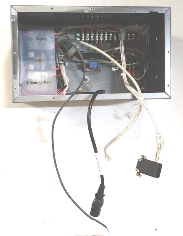
Field Wiring
A 12-position and 4-postion Jones terminal strips connect the various low voltage functions. Three high current SSRs are mounted on the chassis to control fans and water pump. A small relay module is mounted to the rear; it controls the well pump interlock. Power and data cables enter through the rear of the unit.
Four cables connect to the front panel:
1. IEC C-13 AC power
2. DB-15 LV chassis wiring
3. Flue thermocouple is attached directly to PID controller TC input
4. RJ-45 UTP Ethernet for web server
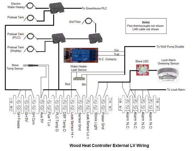
Low Voltage
1. Flue thermocouple – leads are brought directly into the chassis and connect to the PID controller TC inputs. This eliminates need to use a special thermocouple connector and extension cable. The TC has an exposed protective metal braid. I added heat shrink insulation to the portion near the controller to prevent accidental shorts. White and red dots painted on the PID TC input terminals indicate correct TC cable polarity.
2. Stove thermistor – the 10k NTC thermistor is ty-wrapped to the thermocouple cable near the stove flue pipe. This provides rapid sensing of increased temperate when fire is started while not exposing it to excessively high temperature.
3. Greenhouse status and freeze alarm: +5, ground, and freeze leads from greenhouse sensor cable are brought into the controller to drive GH OK and Freeze optocouplers.
4. Leak sensors have two terminations on the terminal strip. An optocoupler relay board N.C, contacts are used to disable the well pump.
5. Display and PLC preheat tank temperature sensors – a 4-postion terminal block located near the preheat tank supplies +5, ground, controller data and display data for the two sensors. The cable continues up to the second floor near the upstairs fan to monitor air temperature far away from the stove. The display data drives the front panel temperature display. Currently three PLC sensors are in use, one located on preheat tank and another in 2nd floor to monitor distant air temperature. A third sensor is mounted under a protective grill on the controller front panel to measure basement air temperature near the stove.
6. Loud alarm – a normally open relay simulates an unsupervised fire alarm sensor. A 4-pos terminal strip provides access to both the normally closed and normally open loud alarm wiring. The controller is connected to the normally open pair. The high temperature sensor located in the ceiling over the stove is connected to the normally closed supervised pair.
7. Stove Work Light – a white LED is mounted on the ceiling above the stove. To dress it up a little mounted it on a piece of aluminum step flashing and cut out a circular insulator from a piece of Teflon to protect the soldered connections.
8. An Ethernet cable connects to the WebControl8 LAN port. The LAN Ethernet switch is located behind the controller so I just ran a patch cable from the controller to the switch rather than installing a “real” Ethernet drop to the chassis as I did with the greenhouse controller.
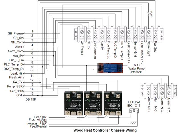
AC
1. IEC C13 receptacle brings AC to the controller.
2. Three chassis mounted SSRs are hardwired to AC wiring.
3. Preheat circulate pump is hardwired to pump control SSR.
4. Fresh air fan is plugged into a dedicated receptacle behind the stove controlled by its SSR.
5. A pair of small computer fans plug into a dedicated SSR controlled receptacle located above the stove blowing air up through a grate in the floor. Another much larger fan, plugged into a dedicated receptacle in an upstairs closet blows air back into the basement.
Appendix A – Schematic
Except for SSRs, leak relay and field wiring terminal strips all major components are mounted on the front panel. A small plastic enclosure isolates AC components: IEC inlet, fuse, NEMA 5-15R socket for DC power supply and a small SSR to switch PID controller power.
Interface logic is mounted on a 4x6 proto board and the WebControl8 PCB is mounted on standoffs above it. A DB-15 male socket connects low voltage wiring in the chassis.


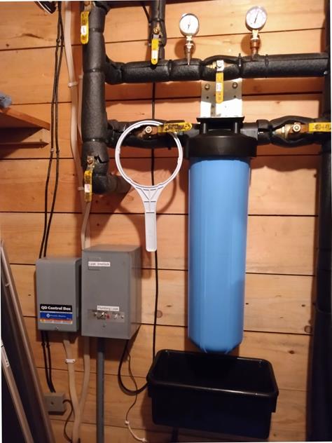
Appendix B – Well Pump Interlock
The well pump interlock is a separate box located next to the submersible pump controller. It consists of a 240V transformer, rectifier and high current 24V relay. When the pressure switch detects low water pressure it applies power to the transformer. Under normal conditions this causes the high current relay to actuate applying power to the well pump. During a leak the wood heat controller opens the N.C. relay contacts wired in series with the well pump low voltage relay coil, preventing it from actuating. The interlock has two LEDs, blue indicates pump is on, the red leak status. Note: the controller is only powered when the pressure switch contacts are closed. A toggle switch bypasses the contacts on the wood heat controller leak relay allowing normal pump operation. A test button applies a 4,700 ohm resistor to the leak detection circuit simulating a leak.

Appendix C – WebControl8 Configuration Pages
There are several web based configuration pages that determine system operation.
Network Setup
This page selects DHCP or static configuration. It also allows setting the NetBIOS name. Web access to the controller can be unrestricted or require username/password login.
WebControl8 time can be set automatically via NTP or manually. The controller does not have a built in battery backed real time clock, time must be set each time controller is powered up or it is set to firmware default date/time. I run my own LAN based NTP time server so point the controller at that time server rather than one on the Internet.
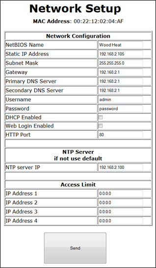
Pressing “Send” updates network settings and reboots the PLC. This is a handy
way to reset the PLC remotely even when not making any changes to network
settings.
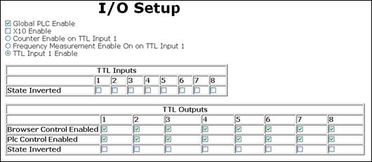
I/O Setup
Individual outputs can be configured to allow PLC control and direct browser control. In most cases PLC code will eventually force the output to correct value even if web browser attempts to set or reset it. For critical outputs the browser interface can be disabled.
The active polarity of the outputs is set from this page.
Temperature Sensor Setup
Dallas 18B20 1-wire temperature sensors are individually serialized. The controller detects attached temperature sensors at power up but they must be manually assigned to a particular sensor ID and measurement units specified.

Notify Setup
Email can be set up to use any TCP/IP port but the unit does not support SSL. In addition to email this page also configures HTTP GETs (not used in this example). I have my own hosted domain so was able to configure mail on a non-standard power and not use SSL; this will be a significant problem going forward limiting the utility of the WebControl8.
Up to eight email messages may be configured and each may be sent to a different email address. I noticed a problem setting message body text with some web browsers (Firefox, chrome, IE10) the second character of each line after the first is lost.

Appendix D – WebControl8 PLC Code
*********** Change Log *********************
10/2/2021 Unit is sensitive to spurious activation. Added low pass filters
to plumbing leak and greenhouse power monitor.
9/22/2021 Added Leak detection code and modified greenhouse freeze and
power failure code to reflect hardware changes.
9/18/2021 Finished debugging hardware changes to implement leak detection.
8/18/2021 1) Changed tricolor LED source to constant 9V from 9V switched in
prep for manual fan switch install.
2) Changed tricolor LED current limiting resistors to 10k from 1k to
reduce brightness.
3) Changed fan SSR control pwr to 5VAux in prep for manual fan
switch install.
4) Multi-voltage feedback problem due to end of string 1-wire temp
sensor 10k data terminator, removed. This was an app note
recommendation for very long circuits. Used it for greenhouse temp
sensor, does not appear to have any benefit for wood heat controller.
5)Installed 5V relay module on chassis in prep for plumbing leak
feature.
6/30/2021 Moved auto on thermistor closer to flue pipe to reduce thernal
lag. Increased auto turn on threshold from 2.55V to 2.65V to
eliminate false activation due to heat pump basement heat.
Should be good at about 64F - 68F delta.
6/302021 Began documenting rework to add water leak detection and manual
turn on of fans to move more air into the basement.
4/28/2021 Heatpump in basement is confusing the woodstove auto power up
circuit as it is rasing differential temperature between stove
and internal temp sensor. To-Do - need to increase the
differential temperature for auto power on
3/15/2021 Wired well pump leak interlock in anticipation of adding water leak
detection. When controller detects a leak opens low voltage relay
circuit preventing well pump from comming on. Interlock has bypass
switch to override leak detection.
Long overdue project, sleeved electric water heater power feed with
3/4" flexable conduit for protection.
11/22/2019 Replaced fresh air duct fan with Tjernlund EF-6 180 CFM free air
150 CFM w/25 feet duct. Hopefully this will move a little more
air to minimized backdraft due to house depressureization.
11/17/2018 Replaced fresh air duct fan with Suncourt DB206C 160CFM. Old fan was
noisy but moved more air, 240CFM. See how well this one works
it is extremely quiet. Was a little worried about using these duct
boost fan to bring in cold outside air but seem to work fine.
5/31/2017 Added temperature sensor logging same as in greenhouse. VAR8
displays first failed temp sensor during each power cycle.
Cleaned up alarm silence and loud alarm code.
1/26/2017 Replaced 74LS38 LED drivers with 74LS26 and moved feed from 5V_PLC
to SW_9v to reduce load on PLC 5 volt linear regulator.
12/1/2015 Smaller fan motor did not move enough makeup air, still getting
chimney downdraft when greenhouse, dryer and bathroom fans run
simultaneously. Switched back to the larger motor but drilled out
the mounting holes and inserted rubber grommets to isolate motor
from duct work. Fan seems much quieter now, only time will tell.
10/24/2015 6" fresh air duct fan worked well but was rather loud. Replaced
motor/impeller with a smaller one I had laying around. Power reduced
to 24W. Hopefully it will still move enough air to prevent
depressuration while not bringing in an excessive amount of cold
air.
Moved terminal blocks so condensation drip pan can be located
directly under the uninsulated portion of fresh air duct after fan.
3/27/2015 Replaced 2nd floor fan with identical used Condor, had become noisy.
Same power draw as old one 60W.
3/10/2015 Cleaned and oiled 2nd floor fan, IMC Condor 12 has been in service
for 30 years. Back to running nice and quiet. Took the opportunity
to measure power with Kill-a-Watt 60W.
2/23/2015 Reduced R2 to 120 ohms, original 220 was marginal (another 220 in
greenhouse), controller occasionally missed greenhouse Freeze wink
signal.
Reworked front panel rocker switch circuit and firmware. Pressing
Off kills base drive to Q2 (PLC keep alive). Unless other hardware
is keeping Q1 turned on unit is forced off, works even if PLC has
crashed.
1/30/2015 Fixed intermittent cause by broken solder joint U11 pin 7. Decreased
R5 to 330 ohms. Original 470 was marginal for greenhouse 5V sensing.
1/23/2015 Added second greenhouse wake up mode. House is so tight it tends
to depressurize when the greenhouse fan is used to pump air from
basement to GH. Makeup air is provided by a fresh air fan controlled
by the wood heat controller, it can either run continuously or be
turned on/off with the wood heat controller. GH pulses freeze for
200ms each time the fan is stated and at 0 and 30 minutes past the
hour.
Increased non-heating mode timeout to 35 so controller will never
timeout and shutdown when greenhouse fan is running.
GH freeze signaling now has two modes:
1) GH Freeze alert - when GH temperature nears freezing GH
Controller turns on freeze signal. This wakes up the wood heat
controller if it was off and triggers audible/visual alarm. Alarm
can be silenced but alarm (flashing red LED) is active for the
duration of the freeze event. Resetting freeze signal requires
going into to GH and hitting the freeze reset button.
2) GH Basement fan on - each time GH turns on basement fan to pump
warm air into the greenhouse it pulses the freeze signal for 200ms.
This turns the wood heat controller on, activating the fresh air
fan and resetting the idle timeout counter. FW ignores short
duration freeze signal to prevent triggering freeze alarm.
1/17/2015 Replaced 4" DC fresh air duct fan with 6" 230 CFM (no backpressure)
AC fan 39W. Replaced insulated duct to repair cat damage. Added SSR
to control fan. Modes same as before: constant & auto (on when
controller is on). Higher performance fan seems to have solved the
depressurization backdraft problem when greenhouse basement fan is
running. But it does bring in a lot of cold air increasing the time
it takes to start the house fans.
12/30/2014 Added fan air temp test back to shutdown code but set to 88F.
Changed UROM1/2 temperature to degrees rather then .1F to
make it more user friendly.
12/8/2014 It appears Greenhouse controller 5V occasionally fails for a
few ms. Changed email notification to report each failure,
instead of only once per wood heat controller power cycle.
2/20/2015 update - glitch is caused by voltage droop when humidity
fan is turned on. Need to modify GH controller, remove diode in
PLC power leg and increase bulk capacitance on 9V power rail.
3/16/2014 Changed 18B20 preheat tank display module to thermistor sensor.
Old display displayed incorrect temp on rare occasions requiring a
power cycle to clear. 1-wire sensor power is always on, assume
display does not due full 1-wire protocol as it only connects to
single sensor and gets confused once in a while because sensor is
alway powered.
2/2/2014 Removed fan air temp from shutdown code. Now system shuts down 55
minutes after flue temp goes below setpoint. This resolves problem
of fans running long into the morning during warmer weather.
Removed dual fan setpoint. Fans come on when air temp >UROM1 in
heating mode, off 2F hysteresis.
1/18/2014 Reduced fan high offset to 5F. During warmer weather never hit hi
threshold so ran too long. Increased UROM1 setpoint to 78F.
12/20/2013 Changed UROM email. At power up email sent if any UROM value is
out of range. Whenever a UROM value is changed email sent indicating
in range or out of range. Note: change is detected by simply
summing all 4 values so if user changes up and another down
may miss change.
12/15/2013 Added dual fan setpoint. Initial set point is value in UROM1. Once
air temp hits UROM1 + 10F set point increased by 10F until next
power cycle. This causes fans to start early in heating cycle while
reducing how long they stay on once stove dies down.
9/2/2013 Cleaned up how fan function responds to out of range temp setting
and removed end of cycle redundant shutdown code.
6/14/2013 Added HIH-4000 humidity sensor. Display only, reading not used for
control.
4/14/2013 Increased fan on temp to 85F and decreased hysteresis to 4 to reduce
run time. Fans kept running hours after fire died down during warmer
months. Changed turnoff to check fan off state rather than actual
temp.
Fixed fan over temp bug, OT warning never turned off
4/3/2013 Upgraded to FW 3.2.17b
3/30/2013 Installed
3/29/2013 FW is sensitive to browser. Editing email text with FF, Chrome
IE 10 corrupts 2nd character. IE 8 is fine. Reported bug to CAI.
Told Works fine in IE 8 so good enough.
3/21/2013 CAI Networks confirmed temp status bug still exists in ver 3.2.16c.
I submitted 2nd bug report when developing wood heat controller
using ver 3.2.11. Same bug I reported when developing greenhouse
controller. Confirmed fix in FW version 3.2.17b.
3/18/2013 Code start
12/30/2012 Project start
*************** PCB Hardware/Firmware version ****************
Hardware: 2.2.2
Firmware: 3.2.17b
Customer loop executed every ~50ms (minimal test code) 65ms-ish (real code)
VAR and RAM initialized to 0 by system at power up
To reset PLC to power up state - update network settings (Send)
RAM location reset to 0 on code upload, VAR not affected
WebControl8 takes about 400ms to init I/O at power up
Per CAI Support Temp sensors take up to 2 sec to stabilize at power up
Email takes about 1.5 sec to send, no timeout if SMTP server does not respond
TTL inputs have 10k pulldown
Output buffers 10mA per output, 30mA total
A/D 10V full scale 10-bits
9V Power consumption
50ma Standby - always on portion of interface board.
175ma PLC only (Live Ethernet serving web page)
360ma Active - PLC, interface board, indicator LEDs
15ma Each SSR
100ma white wood stove illumination LED
***************** I/O Defs **********************
Analog Inputs
-------------
AIP1 - not used
AIP2 - not used
AIP3 - Aux 5V
Digital Inputs
--------------
IP1 - /Stove On
IP2 - /Flue Temp Hi (<900F)
IP3 - Not used (pulled up)
IP4 - GH OK (Active Hi 9/18/2021)
IP5 - Water leak (Added 9/18/2021)
IP6 - GH Freeze (Active Hi 9/18/2021)
IP7 - Silence PB
IP8 - /Flue Temp Lo (<300F)
Digital Outputs
---------------
OP1 - Keep Alive
OP2 - /GH OK LED
OP3 - Air Temp Hi LED
OP4 - Fans
OP5 - Preheat Pump
OP6 - Audible Alarm
OP7 - Loud Alarm
OP8 - not used
Temperature Sensors
-------------------
T1 - Basement near stove
T2 - 2fl closet
T3 - Not used
T4 - Not used
T5 - Not used
T6 - Not used
T7 - Wood_water_storage
T8 - Not used
Temp Sensor status (1 = OK)
------------------
TS1
TS2
TS3
TS4
TS5
TS6
TS7
TS8
Humidity Sensor
---------------
H1 - Display only
Email message Identifiers
-------------------------
EM1 - End of session email
EM2 - Greenhouse failure
EM3 - Temp sensor failure
EM4 - UROM value out of bounds
EM5 - UROM value within bounds
EM6 - Plumbing leak
EM7 -
EM8 -
Variables
--------
VAR1 - Operating mode 1=heating, 0=other (GH freeze, plumbing leak, manual on)
VAR2 - Cycle start basement temperature
VAR3 - Cycle start upstairs temperature
VAR4 - Shutdown idle timer (100=normal,0-59 35-min non-heating, 55-min heating)
VAR5 - Alarm silence timer (100=normal,101=silence period over,
0-59 5-min silent period)
VAR6 -
VAR7 - Bad temp sensor state 0=send email, 1-100 debounce, 101 email sent
VAR8 - First failed temp sensor ID this power cycle
RAM
---
RAM1 - Scratch
RAM2 -
RAM3 -
RAM4 -
RAM5 -
RAM6 - Plumbing leak go/no (0=OK 1=debounced leak status >500ms email sent
RAM7 - Sum of current UROM values
RAM8 - Greenhouse go/nogo and freeze (0=OK, 1=debounced freeze status >500ms
2=GH fail email sent)
Web constants
------------
UROM1 - Fans on - Limits: 60 - 100F (1F hysteresis)
UROM2 - Preheat pump on - Limits: 120 - 160F (2F hysteresis)
UROM3 - Not used
UROM4 - Loud Alarm enable (1=on 0=off)
**************************************************
MODEDET
Sets heating mode flag, based on flue temp.
Delay at power up to allow temp sensors to stabilize.
Sets VAR/RAM registers to default value.
Activates SW controlled power control on to keep unit active even if all
hardware power controls become inactive. Hardware one-shot maintains power
until software is able to take command.
If any UROM values set out of range send notification email at powerup.
FANS
Basement and 2nd fl fans, setpoint in UROM1 with 1F hysteresis.
Measured by temp sensor behind front panel.
Fans only run in heating mode.
If UROM1 value out of range fans forced on at 105F.
Fan alarm triggered at 115F - regardless of heating mode flag in
case PID controller fails.
Front panel switch can force fans on even if PLC is not active.
HWPUMP
Preheat tank recirculate pump. When tank reaches setpoint (UROM2) transfers
water from electric water heater to preheat storage tank. Controlled by temp
sensor on preheat tank outlet.
GRHOUSE
Monitors greenhouse OK and freeze status. Both freeze and GH OK failure
wakes up cntrl. GH OK wakeup is capacitively coupled so cntrl can be
manually shut down in the event of massive problems with greenhouse
controller, (loss of 5V power).
RAM8=1 is debounced freeze state. If freeze <500ms interpreted as GH
controller wakeup event prior to turning on basement fan. GH controller
also pulses freeze at 0 and 30 minutes past the hour to insure wood
stove idle timer does not shut off the fresh air fan. Whenever cntrl is
on so is the fresh air fan, used to minimize problems depressurizing the
house.
Failure of either causes alarm to sound.
If GH OK state is bad email sent and RAM8 flag set to 2 indicating GH is
untrustworthy. RAM8 =2 Flag set and email sent when first detected, reset
to 0 if 5V comes back. Freeze email is sent directly from the greenhouse
cntrl.
PMBLEAK
Leak hardware controlls leak LED directly (grn or flashing red). When leak is
detected power is cut to well pump via the interlock unit located near pump
controller. Monitoring can be disabled by placing toggle switch to ignore,
this kills power to the front panel LED and detection circuit. Well pump
interlock is controlled by a N.C. relay so well pump operates normally.
Upon leak detection sensor debounced (500ms), email sent, RAM6 set to 1.
ALARM
Monitors flue, air, plumbing leak and greenhouse freeze
sounds audible alarm. Front panel PB temporally silences flue and air over
temp and permanently silences leak and greenhouse freeze until next power
cycle if error condition persists.
LDALARM
If front panel alarm ignored for more than a few minutes activates external
alarm that is part of house fire alarm system. To make alarm more noticeable
toggled on/off every 3 seconds. Loud alarm is enabled/disabled by UROM 4.
TSENSOR
Monitors 1-wire temp sensor status, debounces bad status and if bad for a
long time generates email. Logs failed sensor ID in VAR8 even if it is only
for a short time.
UROMCHG
Sums all 4 UROM values. Sends in bound or out of bound email once per change
event.
SHUTDOWN
Monitors system status and if nothing useful to do enters shutdown time
delay. Longer delay used when in heating mode. If unit is in heating mode
sends end of session email.
******************* Code *************************
START
CALLSUB MODEDET
CALLSUB FANS
CALLSUB HWPUMP
CALLSUB GRHOUSE
CALLSUB PMBLEAK
CALLSUB ALARM
CALLSUB LDALARM
CALLSUB TSENSOR
CALLSUB UROMCHG
CALLSUB SHUTDOWN
END
MODEDET:
TSTEQ OP1 0
CALLSUB STARTDLY
TSTEQ IP8 1
SET VAR1 1
RET
STARTDLY:
SET OP1 1
DELAY 10000
SET VAR1 0
SET VAR2 T1
SET VAR3 T2
SET VAR4 100
SET VAR5 100
SET VAR6 0
SET VAR7 100
SET VAR8 0
SET RAM1 0
SET RAM2 0
SET RAM3 0
SET RAM4 0
SET RAM5 0
SET RAM6 0
ADD UROM1 UROM2 RAM7
ADD UROM3 RAM7 RAM7
ADD UROM4 RAM7 RAM7
SET RAM8 0
CALLSUB RANGECHK
BZ RANGEOK
EMAIL EM4
RANGEOK:
RET
RANGECHK:
TSTLT UROM1 60
RET
TSTGT UROM1 100
RET
TSTLT UROM2 120
RET
TSTGT UROM2 160
RET
TSTGT UROM3 0
RET
TSTGT UROM4 1
RET
RET
FANS:
TSTGE T1 1150
SET OP3 1
TSTLT T1 1100
SET OP3 0
TSTLT UROM1 60
GOTO FORCEFAN
TSTGT UROM1 100
GOTO FORCEFAN
TSTEQ VAR1 0
RET
MUL UROM1 10 RAM1
TSTGE T1 RAM1
SET OP4 1
SUB UROM1 1 RAM1
MUL RAM1 10 RAM1
TSTLE T1 RAM1
SET OP4 0
RET
FORCEFAN:
TSTGE T1 1050
SET OP4 1
TSTLT T1 1000
SET OP4 0
RET
HWPUMP:
MUL UROM2 10 RAM1
TSTGE T7 RAM1
SET OP5 1
SUB UROM2 2 RAM1
MUL RAM1 10 RAM1
TSTLE T7 RAM1
SET OP5 0
RET
GRHOUSE:
TSTEQ IP4 0
GOTO GHFAIL
TSTEQ IP6 1
GOTO FREEZE
SET OP2 0
SET RAM8 0
RET
GHFAIL:
SET OP2 1
TSTNE RAM8 0
RET
EMAIL EM2
SET RAM8 2
RET
FREEZE:
DELAY 500
TSTEQ IP6 1
SET RAM8 1
TSTEQ IP6 1
SET OP2 1
RET
PMBLEAK:
TSTEQ IP5 1
GOTO LEAK
SET RAM6 0
RET
LEAK:
DELAY 500
TSTEQ IP5 0
RET
TSTEQ RAM6 1
RET
EMAIL EM6
SET RAM6 1
RET
ALARM:
TSTEQ IP2 0
GOTO ACTALM
TSTEQ OP3 1
GOTO ACTALM
TSTNE RAM6 0
GOTO ACTALM
TSTNE RAM8 0
GOTO ACTALM
SET OP6 0
SET OP7 0
SET VAR5 100
RET
ACTALM:
TSTEQ IP7 1
GOTO SETALMDLY
TSTEQ VAR5 100
GOTO SOUNDALM2
TSTEQ VAR5 101
GOTO SOUNDALM1
TSTNE CM VAR5
RET
SET VAR5 101
RET
SETALMDLY:
SET OP6 0
SET OP7 0
ADD CM 5 VAR5
TSTGE VAR5 60
SUB VAR5 60 VAR5
RET
SOUNDALM1:
TSTEQ IP2 0
GOTO SOUNDALM2
TSTEQ OP3 1
GOTO SOUNDALM2
SET OP6 0
SET OP7 0
RET
SOUNDALM2:
SET OP6 1
RET
LDALARM:
TSTEQ OP6 0
RET
TSTEQ UROM4 0
SET OP7 0
TSTEQ UROM4 0
RET
TSTEQ OP6[300000] 1
GOTO LDTOGGLE
RET
LDTOGGLE:
TSTEQ OP7[2000] 1
SET OP7 0
TSTEQ OP7[5000] 0
SET OP7 1
RET
TSENSOR:
AND TS1 TS2 RAM1
AND TS7 RAM1 RAM1
BZ BADSENSOR
SET VAR7 100
RET
BADSENSOR:
TSTNE VAR7 100
GOTO SENSORDLY
SET VAR8 1
TSTEQ TS1 0
GOTO SENSORDLY
SET VAR8 2
TSTEQ TS2 0
GOTO SENSORDLY
SET VAR8 7
TSTEQ TS7 0
GOTO SENSORDLY
SET VAR8 9
SENSORDLY:
TSTEQ VAR7 101
RET
DEC VAR7
TSTNE VAR7 0
RET
EMAIL EM3
SET VAR7 101
RET
UROMCHG:
ADD UROM1 UROM2 RAM1
ADD UROM3 RAM1 RAM1
ADD UROM4 RAM1 RAM1
TSTEQ RAM7 RAM1
RET
SET RAM7 RAM1
CALLSUB RANGECHK
BZ UROMOK
EMAIL EM4
RET
UROMOK:
EMAIL EM5
RET
SHUTDOWN:
TSTEQ IP1 0
GOTO CANXSD
TSTEQ IP2 0
GOTO CANXSD
TSTEQ IP8 1
GOTO CANXSD
TSTNE RAM6 0
GOTO CANXSD
TSTNE RAM8 0
GOTO CANXSD
TSTGE T1 880
GOTO CANXSD
TSTEQ CM VAR4
GOTO OFF
TSTNE VAR4 100
RET
ADD CM 35 VAR4
TSTEQ VAR1 1
ADD CM 55 VAR4
TSTGE VAR4 60
SUB VAR4 60 VAR4
RET
CANXSD:
SET VAR4 100
RET
OFF:
TSTEQ VAR1 1
EMAIL EM1
DELAY 30000
SET OP1 0
DELAY 5000
RET
******************* End **************************
Appendix E – PID Controller Configuration
The PID controller is configured for heating mode with PID feature disabled. Output is turned on when flue temperature is below the heating set point (300F). Alarm 1 is turned on when flue temperature exceeds alarm threshold (900F).
Specific values as follows:
1. AL1 (Alarm 1): 900
2. AL1 mode: Mode 2 absolute value hi
3. AL2 (Alarm 2): Not used
4. AL2 mode: Not used
5. Range: Default I’m not sure what this is for
6. Input: Default Type K thermocouple
7. Proportional band: Off
8. Integral time range: Off
9. Derivative time range: Off
10. Control direction: Heating
11. Control hysteresis: 2
12. Output control mode: default= 20 relay
13. Low analog output: not used
14. High analog output: not used
15. B5L: not used
16. Temperature units: Fahrenheit
17. Lock: 000=unlocked
18. SV set value heating threshold = 300F